Nissan Titan A60. Manual - part 78
AV
SOUND SIGNAL CIRCUIT
AV-137
< DTC/CIRCUIT DIAGNOSIS >
[PREMIUM WITHOUT NAVIGATION]
C
D
E
F
G
H
I
J
K
L
M
B
A
O
P
YES
>> Replace audio unit. Refer to
AV-175, "Removal and Installation"
.
NO
>> Replace satellite radio tuner. Refer to
AV-187, "Removal and Installation"
RIGHT CHANNEL
1.
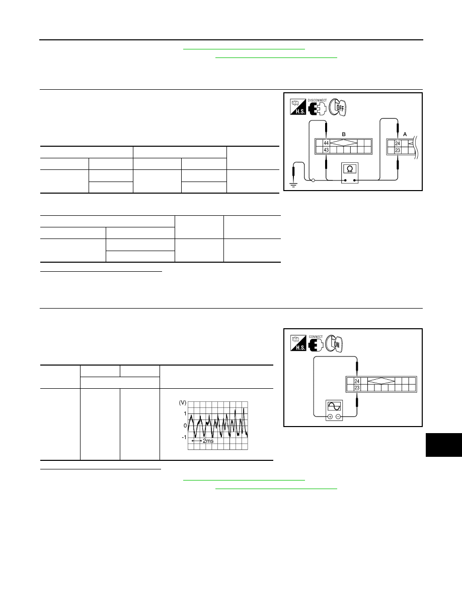
CHECK HARNESS
1. Turn ignition switch OFF.
2. Disconnect satellite radio tuner (factory installed) connector M41
and audio unit connector M170.
3. Check continuity between satellite radio tuner (factory installed)
M41 (A) and audio unit M170 (B).
4. Check continuity between satellite radio tuner (factory installed) connector M41 (A) and ground.
Are continuity results as specified?
YES
>> GO TO 2.
NO
>> Repair harness or connector.
2.
CHECK RIGHT CHANNEL AUDIO SIGNAL
1. Connect satellite radio tuner (factory installed) and audio unit.
2. Turn ignition switch ON.
3. Check signal between satellite radio tuner (factory installed)
connector M41 terminals 23 and 24 with CONSULT-III or oscillo-
scope.
Are voltage readings as specified?
YES
>> Replace audio unit. Refer to
AV-175, "Removal and Installation"
.
NO
>> Replace satellite radio tuner. Refer to
AV-187, "Removal and Installation"
A
B
Continuity
Connector
Terminal
Connector
Terminal
M41
23
M170
43
Yes
24
44
A
—
Continuity
Connector
Terminal
M41
23
Ground
No
24
ALNIA0711GB
Connector
(+)
(-)
Reference signal
Terminals
M41
24
23
ALNIA0881GB
SKIB3609E