Nissan Quest E52. Manual - part 25


  Index      Nissan     Nissan Quest E52 (2011-2014 year) - Service and Repair Manual


Search            


Content   ..  23  24  25  26   ..


Nissan Quest E52. Manual - part 25


LIFTING MOTOR (REAR)

ADP-93

< DTC/CIRCUIT DIAGNOSIS >

C

D

E

F

G

H

I

K

L

M

A

B

ADP

N

O

P

LIFTING MOTOR (REAR)

Component Function Check

INFOID:0000000009649684

1.

CHECK FUNCTION

1.

Select “SEAT LIFTER RR” in “Active test” mode with CONSULT.

2.

Check the lifting motor (rear) operation.

Is the operation of relevant parts normal?

YES

>> INSPECTION END

NO

>> Refer to 

ADP-93, "Diagnosis Procedure"

.

Diagnosis Procedure

INFOID:0000000009649685

1.

CHECK LIFTING MOTOR (REAR) INPUT SIGNAL

1.

Turn ignition switch OFF.

2.

Disconnect lifting motor (rear) connector.

3.

Turn ignition switch ON.

4.

Perform “Active test” (“SEAT LIFTER RR”) with CONSULT.

5.

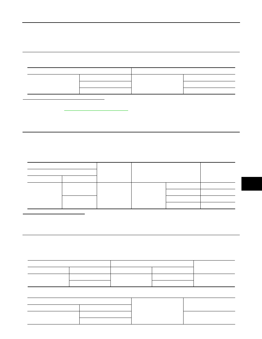
Check voltage between lifting motor (rear) harness connector and ground.

Is the inspection result normal?

YES

>> Replace lifting motor (rear) (built in seat cushion frame).

NO

>> GO TO 2.

2.

CHECK LIFTING MOTOR (REAR) CIRCUIT

1.

Turn ignition switch OFF.

2.

Disconnect driver seat control unit connector.

3.

Check continuity between driver seat control unit harness connector and lifting motor (rear) harness con-
nector.

4.

Check continuity between driver seat control unit harness connector and ground.

Test item

Description

SEAT LIFTER RR

OFF

Seat lifting (rear)

Stop

UP

Upward

DWN

Downward

(+)

(-)

Condition

Voltage (V)

Lifting motor (rear)

Connector

Terminals

B556

41

Ground

SEAT LIFTER RR

OFF

0 – 1

Upward

9 – 16

42

OFF

0 – 1

Downward

9 – 16

Driver seat control unit

Lifting motor (rear)

Continuity

Connector

Terminal

Connector

Terminal

B551

41

B556

41

Existed

42

42

Driver seat control unit

Ground

Continuity 

Connector

Terminal

B551

41

Not existed

42

ADP-94

< DTC/CIRCUIT DIAGNOSIS >

LIFTING MOTOR (REAR)

Is the inspection result normal?

YES

>> Replace driver seat control unit. Refer to 

ADP-111, "Removal and Installation"

.

NO

>> Repair or replace harness or connector.

DOOR MIRROR MOTOR

ADP-95

< DTC/CIRCUIT DIAGNOSIS >

C

D

E

F

G

H

I

K

L

M

A

B

ADP

N

O

P

DOOR MIRROR MOTOR

Component Function Check

INFOID:0000000009649686

1.

CHECK DOOR MIRROR MOTOR FUNCTION

Check the operation with “MIRROR MOTOR RH” and “MIRROR MOTOR LH” in “ACTIVE TEST” mode with
CONSULT
Refer to 

ADP-21, "CONSULT Function"

.

Is the inspection result normal?

YES

>> INSPECTION END

NO

>> Refer to 

ADP-95, "Diagnosis Procedure"

.

Diagnosis Procedure

INFOID:0000000009649687

1.

CHECK DOOR MIRROR MOTOR INPUT SIGNAL

1.

Turn ignition switch OFF.

2.

Disconnect door mirror connector.

3.

Turn ignition switch ON.

4.

Check voltage between door mirror harness connector and ground.

[Driver side]

[Passenger side]

Is the inspection result normal?

YES

>> GO TO 3.

NO

>> GO TO 2.

2.

CHECK DOOR MIRROR MOTOR CIRCUIT

1.

Turn ignition switch OFF.

2.

Disconnect automatic drive positioner control unit connector.

3.

Check continuity between automatic drive positioner control unit harness connector and door mirror har-
ness connector.

(+)

(-)

Condition

Voltage (V)

Door mirror 

Connector

Terminals

D43

10

Ground

Door mirror remote control switch

DOWN / RIGHT

9 – 16

Other than the above

0 – 1

11

LEFT

9 – 16

Other than the above

0 – 1

12

UP

9 – 16

Other than the above

0 – 1

(+)

(-)

Condition

Voltage (V)

Door mirror 

Connector

Terminals

D3

10

Ground

Door mirror remote control switch

DOWN / RIGHT

9 – 16

Other than the above

0 – 1

11

LEFT

9 – 16

Other than the above

0 – 1

12

UP

9 – 16

Other than the above

0 – 1

ADP-96

< DTC/CIRCUIT DIAGNOSIS >

DOOR MIRROR MOTOR

[Driver side]

[Passenger side]

4.

Check continuity between automatic drive positioner control unit harness connector and ground.

[Driver side]

[Passenger side]

Is the inspection result normal?

YES

>> Replace automatic drive positioner control unit. Refer to 

ADP-112, "Removal and Installation"

.

NO

>> Repair or replace harness or connector.

3.

CHECK DOOR MIRROR MOTOR

Check door mirror motor.
Refer to 

ADP-96, "Component Inspection"

.

Is the inspection result normal?

YES

>> Check intermittent incident.Refer to 

GI-42, "Intermittent Incident"

.

NO

>> Replace door mirror motor.

Component Inspection

INFOID:0000000009649688

1.

CHECK DOOR MIRROR MOTOR 1

Check that door mirror motor does not trap foreign objects and does not have any damage.
Refer to 

MIR-31, "Exploded View"

.

Is the inspection result normal?

YES

>> GO TO 2.

NO

>> Replace door mirror.

2.

CHECK DOOR MIRROR MOTOR 2

1.

Turn ignition switch OFF.

2.

Disconnect door mirror connector.

3.

Apply 12 V to each power supply terminal of door mirror motor terminals.

Automatic drive positioner control unit

Door mirror

Continuity

Connector

Terminal

Connector

Terminal

M75

12

D43

10

Existed

23

12

24

11

Automatic drive positioner control unit

Door mirror

Continuity

Connector

Terminal

Connector

Terminal

M75

10

D3

12

Existed

11

11

22

10

Automatic drive positioner control unit

Ground

Continuity 

Connector

Terminal

M75

12

Not existed

23

24

Automatic drive positioner control unit

Ground

Continuity 

Connector

Terminal

M75

10

Not existed

11

22


Content   ..  23  24  25  26   ..