Nissan Versa Note. Manual - part 797


  Index      Nissan     Nissan Versa Note (2014 year) - Service and Repair Manual


Search            


Content   ..  795  796  797  798   ..


Nissan Versa Note. Manual - part 797


TM-68

< SYSTEM DESCRIPTION >

[CVT: RE0F11A]

STRUCTURE AND OPERATION

STRUCTURE AND OPERATION

TRANSAXLE
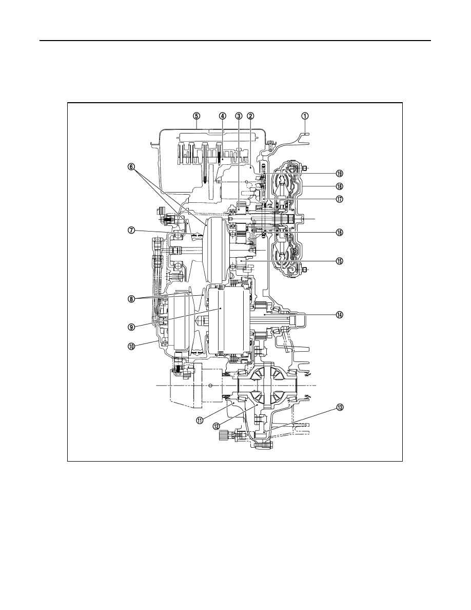
TRANSAXLE : Cross-Sectional View

INFOID:0000000009019604

TRANSAXLE : Transaxle Mechanism

INFOID:0000000009019605

BELT & PULLEY

1.

Converter housing 

2.

Oil pump

3.

Counter drive gear

4.

Control valve

5.

Oil pan

6.

Primary pulley 

7.

Steel belt

8.

Secondary pulley

9.

Planetary gear (auxiliary gearbox) 

10.

Side cover

11.

Transaxle case

12.

Differential case

13.

Final gear

14.

Reduction gear

15.

Counter driven gear

16.

Drive sprocket 

17.

Oil pump chain 

18.

Torque converter

19.

Driven sprocket

JSDIA1777ZZ

STRUCTURE AND OPERATION

TM-69

< SYSTEM DESCRIPTION >

[CVT: RE0F11A]

C

E

F

G

H

I

J

K

L

M

A

B

TM

N

O

P

Mechanism

It is composed of a pair of pulleys (the groove width is changed freely in the axial direction) and the steel belt

(the steel plates are placed continuously and the belt is guided with the multilayer steel rings on both sides).

The groove width changes according to wrapping radius of steel belt and pulley from low status to overdrive

status continuously with non-step. It is controlled with the oil pressures of primary pulley and secondary pulley.

Steel belt

It is composed of multiple steel plates (A) and two steel rings (B)

stacked to a several number. The feature of this steel belt transmits

power with compression of the steel plate in contrast with transmis-

sion of power in pulling with a rubber belt. Friction force is required

with the pulley slope to transmit power from the steel plate. The force

is generated with the following mechanism:

Oil pressure applies to the secondary pulley to nip the plate. 

⇒The

plate is pushed and extended outward. 

⇒The steel ring shows with-

stands. 

⇒Pulling force is generated on the steel ring. ⇒The plate of

the primary pulley is nipped between the pulley. 

⇒Friction force is

generated between the steel belt and the pulley. 

Therefore, responsibilities are divided by the steel plate that trans-

mits the power with compression and the steel ring that maintains necessary friction force.   In this way, the

tension of the steel ring is distributed on the entire surface and stress variation is limited, resulting in good

durability. 

Pulley

The primary pulley (input shaft side) and the secondary pulley (output shaft side) have the shaft with slope

(fixed cone surface), movable sheave (movable cone surface that can move in the axial direction) and oil pres-

sure chamber at the back of the movable sheave. 

Pulley gear shifting operation 

• Pulley gear shifting operation 

The movable sheave slides on the shaft to change the groove width of the pulley. Input signals of engine

load (accelerator pedal opening), engine revolution and gear ratio (vehicle speed) change the operation

pressures of the primary pulley and the secondary pulley, and controls the pulley groove width.   Along with

change of the pulley groove width, the belt contact radius is changed. This allows continuous and stepless

JSDIA1966ZZ

JSDIA1779GB

TM-70

< SYSTEM DESCRIPTION >

[CVT: RE0F11A]

STRUCTURE AND OPERATION

gear shifting from low to overdrive. “The contact radius ratio of each pulley in contact with the belt x auxiliary

gearbox gear ratio” is the gear ratio. 

AUXILIARY GEARBOX MECHANISM

1st, 2nd and reverse gears are changed with the planetary gear mechanism. 

TRANSAXLE : Operation Status

INFOID:0000000009019606

×: Engaged or applied.

JSDIA2573GB

Slector le-

ver posi-

tion

Parking 
mecha-

nism

Counter 
gear set 

Low brake  High clutch

Reverse 

brake 

Primary 

pulley 

Secondary 

pulley

Steel belt

Reduction 

gear set

P

×

×

×

×

×

R

×

×

×

×

×

×

N

×

×

×

×

D

×

× (1GR)

× (2GR)

×

×

×

×

L

×

× (1GR)

× (2GR)

×

×

×

×

STRUCTURE AND OPERATION

TM-71

< SYSTEM DESCRIPTION >

[CVT: RE0F11A]

C

E

F

G

H

I

J

K

L

M

A

B

TM

N

O

P

TRANSAXLE : Oil Pressure System 

INFOID:0000000009019607

Oil pressure required for operation of the transaxle transmission mechanism is generated by oil pump, oil

pressure control valve, solenoid valve, etc. 

TRANSAXLE : Component Description

INFOID:0000000009019608

JSDIA1826GB

Part name

Function

Torque converter

It is composed of the cover converter, turbine assembly, stator, pump impeller assem-
bly, etc. It increases the engine torque and transmits the power to the transaxle. 

Oil pump

Through the oil pump drive chain, it uses the vane oil pump driven by the engine. It gen-
erates necessary oil pressure to circulate fluid and to operate the clutch and brake. 

Counter gear set

The power from the torque converter is transmitted to the primary pulley through the 
counter drive gear and the counter driven gear. 

Belt & pulley (Continuously variable transmis-
sion)

It is composed of the primary pulley, secondary pulley, steel belt, etc. and the mecha-
nism performs shifting, changes the gear ratio and transmits the power with oil pressure 
from the control valve. 

Auxiliary gearbox (stepped transmission) 

It is composed of the planetary gear, multi-disc clutch, multi-disc brake, etc. and the 
mechanism performs shifting (1-2 gear shifting and reverse) with oil pressure from the 
control valve. 

Reduction gear set

Conveys power from the transmission mechanism to the reduction gear and the final 
gear. 

Parking mechanism

When the shift lever is changed to P position, the mechanism fixes the parking gear (in-
tegrated with the reduction gear) and the fixes the output shaft. 

Control valve

Controls oil pressure from the oil pump to the pressure suitable for the line pressure 
control system, shift control system, lock-up control system and lubrication system. 

Pressure regulator valve

Adjusts the discharge pressure from the oil pump to the optimum pressure (line pres-
sure) corresponding to the driving condition.

Torque converter regulator valve

Adjusts the feed pressure to the torque converter to the optimum pressure correspond-
ing to the driving condition. 

Pilot valve

Adjusts line pressure and produces a constant pressure (pilot pressure) necessary for 
activating each solenoid valve.


Content   ..  795  796  797  798   ..