Nissan Versa Note. Manual - part 460


  Index      Nissan     Nissan Versa Note (2014 year) - Service and Repair Manual


Search            


Content   ..  458  459  460  461   ..


Nissan Versa Note. Manual - part 460


FRONT COIL SPRING AND STRUT

FSU-17

< UNIT DISASSEMBLY AND ASSEMBLY >

C

D

F

G

H

I

J

K

L

M

A

B

FSU

N

O

P

5. Compress coil spring using a suitable tool (A).

WARNING:

Make sure that the pawls of the suitable tool are firmly

hooked on the coil spring. The suitable tool must be tight-

ened alternately so as to not tilt the coil spring.

6. Make sure the coil spring is free between the spring upper seat and the strut.
7. Hold the piston rod and remove the piston rod lock nut.
8. Remove strut mount bearing, spring upper seat, and bound bumper as a set.
9. Remove bound bumper from spring upper seat.
10. Gradually release the suitable tool and remove the coil spring.

CAUTION:

Release the suitable tool while making sure the position of the suitable tool on the coil spring

does not move.

11. Remove the Tool from strut.

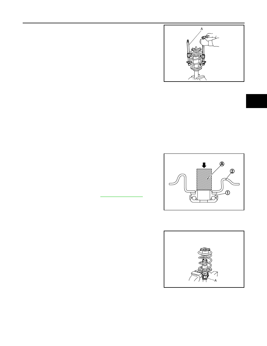
12. If necessary, remove strut mount bearing (1) from spring upper

seat (2), using a Tool (A).

CAUTION:

Do not disassemble the strut mount bearing unless damage

exists.

13. Inspect the components. Refer to 

FSU-18, "Inspection"

.

ASSEMBLY

CAUTION:

Do not damage the piston rod when removing components from the front coil spring and strut.
1. Install Tool (A) to the front coil spring and strut.

CAUTION:

When installing Tool (A), wrap a shop cloth around the front

coil spring and strut to protect the parts from damage.

2. Secure Tool (A) in a vise.

JPEIA0007ZZ

Tool number : ST35652000 ( — )

Tool number : KV10106700 ( — )

JPEIA0228ZZ

Tool number : ST35652000

JPEIA0006ZZ

FSU-18

< UNIT DISASSEMBLY AND ASSEMBLY >

FRONT COIL SPRING AND STRUT

3. Compress coil spring using a suitable tool (A).

WARNING:

Make sure that the pawls of the suitable tool are firmly

hooked on the coil spring. The suitable tool must be tight-

ened alternately so as to not tilt the coil spring.

CAUTION:

Face tube side of coil spring (1) downward. Align the lower

end to lower seat (2).

4. Apply soapy water to bound bumper.

CAUTION:

Do not use machine oil.

5. Insert bound bumper into spring upper seat.
6. Install strut mount bearing, spring upper seat, and bound bumper as a set.

CAUTION:

Do not apply oil, such as grease, when installing the strut mount bearing.

7. Secure piston rod tip so that piston rod does not turn, then install piston rod lock nut and tighten to the

specified torque.

CAUTION:

Do not reuse piston rod lock nut.

8. Gradually release the suitable tool, and remove the suitable tool from the coil spring.

CAUTION:

Release the suitable tool while making sure the position of the suitable tool on the coil spring

does not move.

9. Remove the Tool (A) from the vise.

10. Remove Tool (A) from the front coil spring and strut. 
11. Install strut mount insulator.
12. After replacing the strut, always follow the disposal procedure to

discard the old strut. Refer to 

FSU-19, "Disposal"

.

Inspection

INFOID:0000000009561141

INSPECTION AFTER DISASSEMBLY

Check the following items and replace the parts if necessary.

Strut

• Check the strut for oil leaks, deformation, cracks, or damage.

JPEIA0007ZZ

Maximum gap (A)

:5 mm (0.2 in)

JPEIA0095ZZ

Tool number : ST35652000 ( — )

JPEIA0006ZZ

FRONT COIL SPRING AND STRUT

FSU-19

< UNIT DISASSEMBLY AND ASSEMBLY >

C

D

F

G

H

I

J

K

L

M

A

B

FSU

N

O

P

• Check the piston rod for damage, uneven wear, or distortion.

Strut Mount Insulator and bound bumper

Check the strut mount insulator and the bound bumper for cracks, wear, or damage.

Coil Spring

Check the coil spring for cracks, wear, or damage.

INSPECTION AFTER INSTALLATION

1. Check the wheel sensor harness to be sure the connectors are fully seated.
2. Check the neutral position of the steering angle sensor. Refer to 

BRC-53, "Work Procedure"

.

3. Check the wheel alignment. Refer to 

FSU-7, "Inspection"

.

Disposal

INFOID:0000000009561142

1. Set the strut horizontally with the piston rod fully extended.
2. Drill a 2 – 3 mm (0.08 – 0.12 in) hole at the position ( ) from top

as shown to release gas gradually.

CAUTION:

• Wear eye protection (safety glasses).

• Wear gloves.

• Be careful with metal chips or oil blown out by the com-

pressed gas.

NOTE:
• Drill vertically in this direction (

).

• Drill directly to the outer tube avoiding brackets.

• The gas is clear, colorless, odorless, and harmless.

3. Position the drilled hole downward and drain oil by moving the piston rod several times.

CAUTION:

Dispose of drained oil according to the law and local regulations.

(A) : 20 – 30 mm (0.79 – 1.18 in)

JPEIA0160ZZ

FSU-20

< SERVICE DATA AND SPECIFICATIONS (SDS) 

SERVICE DATA AND SPECIFICATIONS (SDS)

SERVICE DATA AND SPECIFICATIONS (SDS)

SERVICE DATA AND SPECIFICATIONS (SDS)

Wheel Alignment (Unladen*

1

)

INFOID:0000000009561133

*1: Fuel, engine coolant and lubricant are full. Spare tire, jack, hand tools and mats are in designated positions.
*2: The difference when assuming the (LH) side is the standard.

Ball Joint

INFOID:0000000009561134

Camber
Degree minute (Decimal degree)

Minimum

−0° 50′ (−0.83°)

Nominal

−0° 05′ (−0.08°)

Maximum

0

° 40′ (0.67°)

(LH) and (RH) difference

*2

–0

° 45′ (–0.75°) - 0° 45′ (0.75°)

Caster
Degree minute (Decimal degree)

Minimum

3

° 00′ (3.00°)

Nominal

3

° 45′ (3.75°)

Maximum

4

° 30′ (4.50°)

(LH) and (RH) difference

*2

–0

° 45′ (–0.75°) - 0° 45′ (0.75°)

Kingpin inclination
Degree minute (Decimal degree)

Minimum

11

° 00′ (11.00°)

Nominal

11

° 45′ (11.75°)

Maximum

12

° 30′ (12.50°)

Total toe-in

Distance (A - B)

Minimum

 0 mm (0.00 in)

Nominal

In 1 mm (In 0.04 in)

Maximum

In 2 mm (In 0.08 in)

Angle (LH and RH)
Degree minute
(Decimal degree)

Minimum

0

° 00′ 00″ (0.00°)

Nominal

In 0

° 03′ 00″ (In 0.05°)

Maximum

In 0

° 06′ 00″ (In 0.10°)

SFA234AC

Swing torque

0.5 – 3.4 N·m (0.05 – 0.35 kg-m, 4 – 30 in-lb)

Rotating torque

15.4 – 104.7 N (1.6 – 10.7 kg-f, 3.5 – 23.5 lb-f)

Axial end play

.01 mm (0.004 in)


Content   ..  458  459  460  461   ..