Nissan Versa Note. Manual - part 392


  Index      Nissan     Nissan Versa Note (2014 year) - Service and Repair Manual


Search            


Content   ..  390  391  392  393   ..


Nissan Versa Note. Manual - part 392


EM-84

< REMOVAL AND INSTALLATION >

[HR16DE]

CYLINDER HEAD

• After cooling down engine, again check oil/fluid levels including engine oil and engine coolant. Refill to spec-

ified level, if necessary.

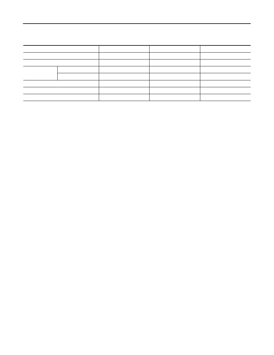
• Summary of the inspection items:

*Power steering fluid, brake fluid, etc.

Item

Before starting engine

Engine running

After engine stopped

Engine coolant

Level

Leaks

Level

Engine oil

Level

Leaks

Level

Transmission/
transaxle fluid 

CVT Models

Leaks

Level/Leaks

Leaks

M/T Models

Level/Leaks

Leaks

Level/Leaks

Other oils and fluids*

Level

Leaks

Level

Fuel

Leaks

Leaks

Leaks

Exhaust gas

Leaks

ENGINE ASSEMBLY

EM-85

< UNIT REMOVAL AND INSTALLATION >

[HR16DE]

C

D

E

F

G

H

I

J

K

L

M

A

EM

N

P

O

UNIT REMOVAL AND INSTALLATION

ENGINE ASSEMBLY

Exploded View

INFOID:0000000009444746

CAUTION:

Check that the stud bolt (*2) is tight at the specified torque before tightening the nut (*1) shown. [Stud

bolt (*2) may be loosened after loosening the nut (*1)]

1.

Engine mounting (RH) stay

2.

Engine mount (RH) stay

3.

Engine mounting insulator (RH)

4.

Rear engine mounting bracket

5.

Rear torque rod

6.

Engine mounting bracket (LH)

7.

Engine mounting bracket (LH)

8.

Engine mounting insulator (LH)

9.

Mass damper

A.

Front mark

B.

Transaxle (lower)

C.

CVT models

AWBIA1586ZZ

EM-86

< UNIT REMOVAL AND INSTALLATION >

[HR16DE]

ENGINE ASSEMBLY

CAUTION:

Check that the stud bolt (*2) is tight at the specified torque before tightening the nut (*1) shown. [Stud

bolt (*2) may be loosened after loosening the nut (*1)]

Removal and Installation

INFOID:0000000009444747

WARNING:

• Position the vehicle on a flat and solid surface.

• Place chocks at front and back of rear wheels.

• Attach proper slingers and bolts described in PARTS CATALOG if engine is not already equipped.

CAUTION:

• Always be careful to work safely.

• Do not start working until exhaust system and coolant are cool enough.

• If items or work required are not covered by the engine section, refer to the applicable sections.

• Always use the support point specified for lifting.

• Use either 2-pole lift type or separate type lift. If board-on type must be used, support the rear axle

jacking point with a transmission jack or similar tool before starting work, in preparation for the

backward shift of center of gravity.

• For supporting points for lifting and jacking point at rear axle, refer to 

GI-29, "2-Pole Lift"

.

NOTE:

• When removing components such as hoses, tubes/lines, etc., cap or plug openings to prevent fluid from

spilling.

1.

Engine mounting (RH) stay

2.

Engine mount (RH) stay

3.

Engine mounting insulator (RH)

4.

Rear engine mounting bracket

5.

Rear torque rod

6.

Engine mounting bracket (LH)

7.

Mass damper

8.

Engine mounting insulator (LH)

9.

Engine mounting bracket (LH)

10. Engine mount bracket (LH)

A.

Front mark

B.

Transaxle (upper)

C.

Transaxle (lower)

D.

M/T models

AWBIA1587ZZ

ENGINE ASSEMBLY

EM-87

< UNIT REMOVAL AND INSTALLATION >

[HR16DE]

C

D

E

F

G

H

I

J

K

L

M

A

EM

N

P

O

• Remove the engine and the transaxle assembly from the vehicle downward. Separate the engine and the

transaxle.

REMOVAL

1. Release fuel pressure. Refer to 

EC-135, "Work Procedure"

.

2. Drain engine coolant from radiator. Refer to 

CO-8, "Draining Engine Coolant"

.

CAUTION:

• Perform this step when the engine is cold.

• Do not spill engine coolant on drive belts.

3. Front fender protector (RH/LH). Refer to 

EXT-36

4. Drive belt: Refer to 

EM-16, "Removal and Installation"

.

5. Battery and battery tray. Refer to 

CHG-29

.

6. Air duct (inlet), air duct, and air cleaner case assembly. Refer to 

EM-26, "Removal and Installation"

.

7. Radiator hose (upper and lower). Refer to 

CO-14

.

8. Exhaust front tube. Refer to 

EX-5

.

9. Disconnect engine room harness connector at the ECM and CVT (if equipped).

CAUTION:

Protect connectors against foreign materials during the operation by wrapping in a plastic bag.

10. Disconnect heater hoses. Refer to 

CO-14, "Exploded View"

.

11. Disconnect fuel feed hose at engine side. Refer to 

EM-40, "Exploded View"

.

12. Disconnect control linkage cable from transaxle. Refer to 

TM-20, "Exploded View"

 (M/T models) and   

TM-

232, "Exploded View"

 (CVT models).

13. Disconnect clutch tube on transaxle side from clutch damper (M/T models). Refer to 

CL-14, "Exploded

View"

.

14. Remove alternator. Refer to 

CHG-29, "Exploded View"

.

15. Disconnect vacuum hose at engine side. 
16. Remove EVAP hoses at engine side. 
17. Remove a/c compressor from the engine with the piping connected. Temporarily position the a/c compres-

sor on the vehicle side with a rope without placing a heavy load on the piping.

18. Remove ground cable at transaxle side.
19. Remove drive shafts (RH/LH). Refer to 

FAX-19, "Removal and Installation"

.

20. Remove rear torque rod (1).

21. When engine can be hoisted, install engine slinger to cylinder

head front left side (A) and rear right side (B) and support the

engine position with a suitable tool.

(2)

: Rear engine mounting bracket

: Front

JSBIA0643ZZ

: Engine front

Slinger (A) bolts 

: 65 N·m (6.6 kg-m, 48 ft-lb)

Slinger (B) bolts 

: 25 N·m (2.6 kg-m, 18 ft-lb)

AWBIA1134GB


Content   ..  390  391  392  393   ..