Nissan Versa Note. Manual - part 313


  Index      Nissan     Nissan Versa Note (2014 year) - Service and Repair Manual


Search            


Content   ..  311  312  313  314   ..


Nissan Versa Note. Manual - part 313


EC-234

< DTC/CIRCUIT DIAGNOSIS >

[HR16DE]

P0139 HO2S2

P0139 HO2S2

DTC Logic

INFOID:0000000009020743

DTC DETECTION LOGIC

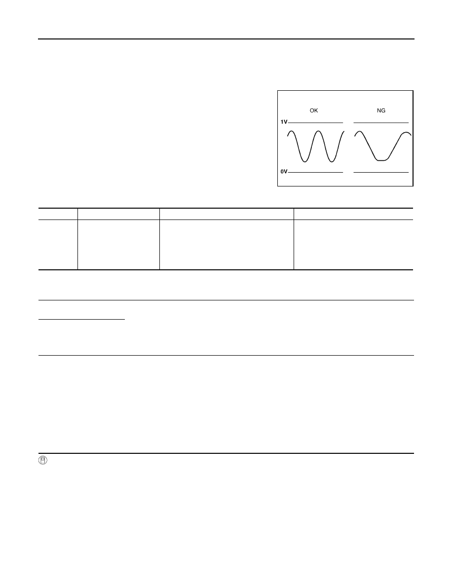
The heated oxygen sensor 2 has a much longer switching time

between rich and lean than the air fuel ratio (A/F) sensor 1. The oxy-

gen storage capacity of the three way catalyst (manifold) causes the

longer switching time. To judge the malfunctions of heated oxygen

sensor 2, ECM monitors whether the switching response of the sen-

sor's voltage is faster than specified during the various driving condi-

tion such as fuel cut.

DTC CONFIRMATION PROCEDURE

1.

INSPECTION START

Do you have CONSULT?

YES

>> GO TO 2.

NO

>> GO TO 6.

2.

PRECONDITIONING

If DTC Confirmation Procedure has been previously conducted, always perform the following procedure

before conducting the next test.

1. Turn ignition switch OFF and wait at least 10 seconds.

2. Turn ignition switch ON.

3. Turn ignition switch OFF and wait at least 10 seconds.

TESTING CONDITION:

For better results, perform “DTC WORK SUPPORT” at a temperature of 0 to 30

°C (32 to 86°F).

>> GO TO 3.

3.

PERFORM DTC CONFIRMATION PROCEDURE

With CONSULT

1. Start engine and warm it up to the normal operating temperature.

2. Turn ignition switch OFF and wait at least 10 seconds.

3. Turn ignition switch ON.

4. Turn ignition switch OFF and wait at least 10 seconds.

5. Start engine and keep the engine speed between 3,500 and 4,000 rpm for at least 1 minute under no load.

6. Let engine idle for 1 minute.

7. Select “DATA MONITOR” mode of “ENGINE” using CONSULT.

8. Make sure that “COOLAN TEMP/S” indicates more than 70

°C (158°F).

If not, warm up engine and go to next step when “COOLAN TEMP/S” indication reaches to 70

°C (158°F).

9. Open engine hood.

10. Select “HO2S2 (B1) P0139” in “DTC WORK SUPPORT” mode of “ENGINE” using CONSULT.

SEF302U

DTC No.

Trouble diagnosis content

DTC detecting condition

Possible cause

P0139

Heated oxygen sensor 2 
circuit slow response

It takes more time for the sensor to respond 
between rich and lean than the specified time.

• Harness or connectors

(The sensor circuit is open or shorted)

• Heated oxygen sensor 2
• Fuel pressure
• Fuel injector
• Intake air leaks

P0139 HO2S2

EC-235

< DTC/CIRCUIT DIAGNOSIS >

[HR16DE]

C

D

E

F

G

H

I

J

K

L

M

A

EC

N

P

O

11. Start engine and follow the instruction of CONSULT display.

NOTE:

It will take at most 10 minutes until “COMPLETED” is displayed.

Is “COMPLETED” displayed on CONSULT screen?

YES

>> GO TO 5.

NO

>> GO TO 4.

4.

PERFORM DTC CONFIRMATION PROCEDURE AGAIN

1. Turn ignition switch OFF and leave the vehicle in a cool place (soak the vehicle).

2. Perform DTC confirmation procedure again.

>> GO TO 3.

5.

PERFORM SELF-DIAGNOSIS

With CONSULT

Perform ECM self-diagnosis.
Is DTC “P0139” detected?

YES

>> Proceed to 

EC-236, "Diagnosis Procedure"

.

NO

>> INSPECTION END

6.

PERFORM COMPONENT FUNCTION CHECK

Perform component function check. Refer to 

EC-235, "Component Function Check"

.

NOTE:

Use component function check to check the overall function of the heated oxygen sensor 2 circuit. During this

check, a 1st trip DTC might not be confirmed.
Is the inspection result normal?

YES

>> INSPECTION END

NO

>> Proceed to 

EC-236, "Diagnosis Procedure"

.

Component Function Check

INFOID:0000000009020744

1.

PERFORM COMPONENT FUNCTION CHECK-I

Without CONSULT

1. Start engine and warm it up to normal operating temperature.

2. Turn ignition switch OFF and wait at least 10 seconds.

3. Start engine and keep the engine speed between 3,500 and 4,000 rpm for at least 1 minute under no load.

4. Let engine idle for 1 minute.

5. Check the voltage between ECM harness connector and ground under the following condition.

Is the inspection result normal?

YES

>> INSPECTION END

NO

>> GO TO 2.

2.

PERFORM COMPONENT FUNCTION CHECK-II

Check the voltage between ECM harness connector and ground under the following condition.

ECM

Condition

Voltage

Connector

Terminal

+

F11

50

(HO2S2 signal)

59

Revving up to 3,600 rpm under no load at 
least 10 times

A change of voltage should be more than 
0.12 V for 1 second during this procedure.

EC-236

< DTC/CIRCUIT DIAGNOSIS >

[HR16DE]

P0139 HO2S2

Is the inspection result normal?

YES

>> INSPECTION END

NO

>> GO TO 3.

3.

PERFORM COMPONENT FUNCTION CHECK-III

Check the voltage between ECM harness connector and ground under the following condition.

Is the inspection result normal?

YES

>> INSPECTION END

NO

>> Go to 

EC-236, "Diagnosis Procedure"

.

Diagnosis Procedure

INFOID:0000000009020745

1.

CHECK GROUND CONNECTION

1. Turn ignition switch OFF.

2. Check ground connection E15. Refer to Ground Inspection in 

GI-44, "Circuit Inspection"

.

Is the inspection result normal?

YES

>> GO TO 2.

NO

>> Repair or replace ground connection.

2.

CLEAR THE MIXTURE RATIO SELF-LEARNING VALUE

1. Clear the mixture ratio self-learning value. Refer to 

EC-130, "Work Procedure"

.

2. Run engine for at least 10 minutes at idle speed.
Is the 1st trip DTC P0171 or P0172 detected? Is it difficult to start engine?

YES

>> Perform trouble diagnosis for DTC P0171 or P0172. Refer to 

EC-245, "DTC Logic"

 or 

EC-249,

"DTC Logic"

.

NO

>> GO TO 3.

3.

CHECK HO2S2 GROUND CIRCUIT FOR OPEN AND SHORT

1. Turn ignition switch OFF.

2. Disconnect heated oxygen sensor 2 (HO2S2) harness connector.

3. Disconnect ECM harness connector.

4. Check the continuity between HO2S2 harness connector and ECM harness connector.

5. Also check harness for short to ground and short to power.
Is the inspection result normal?

YES

>> GO TO 4.

NO

>> Repair open circuit or short to ground or short to power in harness or connectors.

4.

CHECK HO2S2 INPUT SIGNAL CIRCUIT FOR OPEN AND SHORT

ECM

Condition

Voltage

Connector

Terminal

+

F11

50

(HO2S2 signal)

59

Keeping engine speed at idle for 10 minutes

A change of voltage should be more than 
0.12 V for 1 second during this procedure.

ECM

Condition

Voltage

Connector

Terminal

+

F11

50

(HO2S2 signal)

59

Coasting from 80 km/h (50 MPH) in D position 
(CVT), 4th gear position (M/T) 

A change of voltage should be more than 
0.12 V for 1 second during this procedure.

HO2S2

ECM

Continuity

Connector

Terminal

Connector

Terminal

E63

1

F11

59

Existed

P0139 HO2S2

EC-237

< DTC/CIRCUIT DIAGNOSIS >

[HR16DE]

C

D

E

F

G

H

I

J

K

L

M

A

EC

N

P

O

1. Check the continuity between HO2S2 harness connector and ECM harness connector.

2. Check the continuity between HO2S2 harness connector or ECM harness connector and ground.

3. Also check harness for short to power.
Is the inspection result normal?

YES

>> GO TO 5.

NO

>> Repair open circuit or short to ground or short to power in harness or connectors.

5.

CHECK HEATED OXYGEN SENSOR 2

Refer to 

EC-237, "Component Inspection"

.

Is the inspection result normal?

YES

>> GO TO 6.

NO

>> Replace heated oxygen sensor 2. Refer to 

EX-5, "Exploded View"

.

6.

CHECK INTERMITTENT INCIDENT

Refer to 

GI-41, "Intermittent Incident"

.

>> INSPECTION END

Component Inspection

INFOID:0000000009020746

1.

INSPECTION START

Do you have CONSULT?

YES

>> GO TO 2.

NO

>> GO TO 3.

2.

CHECK HEATED OXYGEN SENSOR 2

With CONSULT

1. Turn ignition switch ON and select “ENGINE” using CONSULT.

2. Select “DATA MONITOR” mode.

3. Start engine and warm it up to the normal operating temperature.

4. Turn ignition switch OFF and wait at least 10 seconds.

5. Start engine and keep the engine speed between 3,500 and 4,000 rpm for at least 1 minute under no load.

6. Let engine idle for 1 minute.

7. Select “FUEL INJECTION” in “ACTIVE TEST” mode, and select “HO2S2 (B1)” as the monitor item with

CONSULT.

HO2S2

ECM

Continuity

Connector

Terminal

Connector

Terminal

E63

4

F11

50

Existed

HO2S2

Ground

Continuity

Connector

Terminal

E63

4

Ground

Not existed

ECM

Ground

Continuity

Connector

Terminal

F11

50

Ground

Not existed


Content   ..  311  312  313  314   ..