Nissan Versa Note. Manual - part 28


  Index      Nissan     Nissan Versa Note (2014 year) - Service and Repair Manual


Search            


Content   ..  26  27  28  29   ..


Nissan Versa Note. Manual - part 28


AV-104

< DTC/CIRCUIT DIAGNOSIS >

[DISPLAY AUDIO]

BLUETOOTH® VOICE SIGNAL CIRCUIT

Is the inspection result normal?

YES

>> Replace Bluetooth

®

 control unit. Refer to 

AV-123, "Removal and Installation"

.

NO

>> Replace audio unit. Refer to 

AV-118, "Removal and Installation"

.

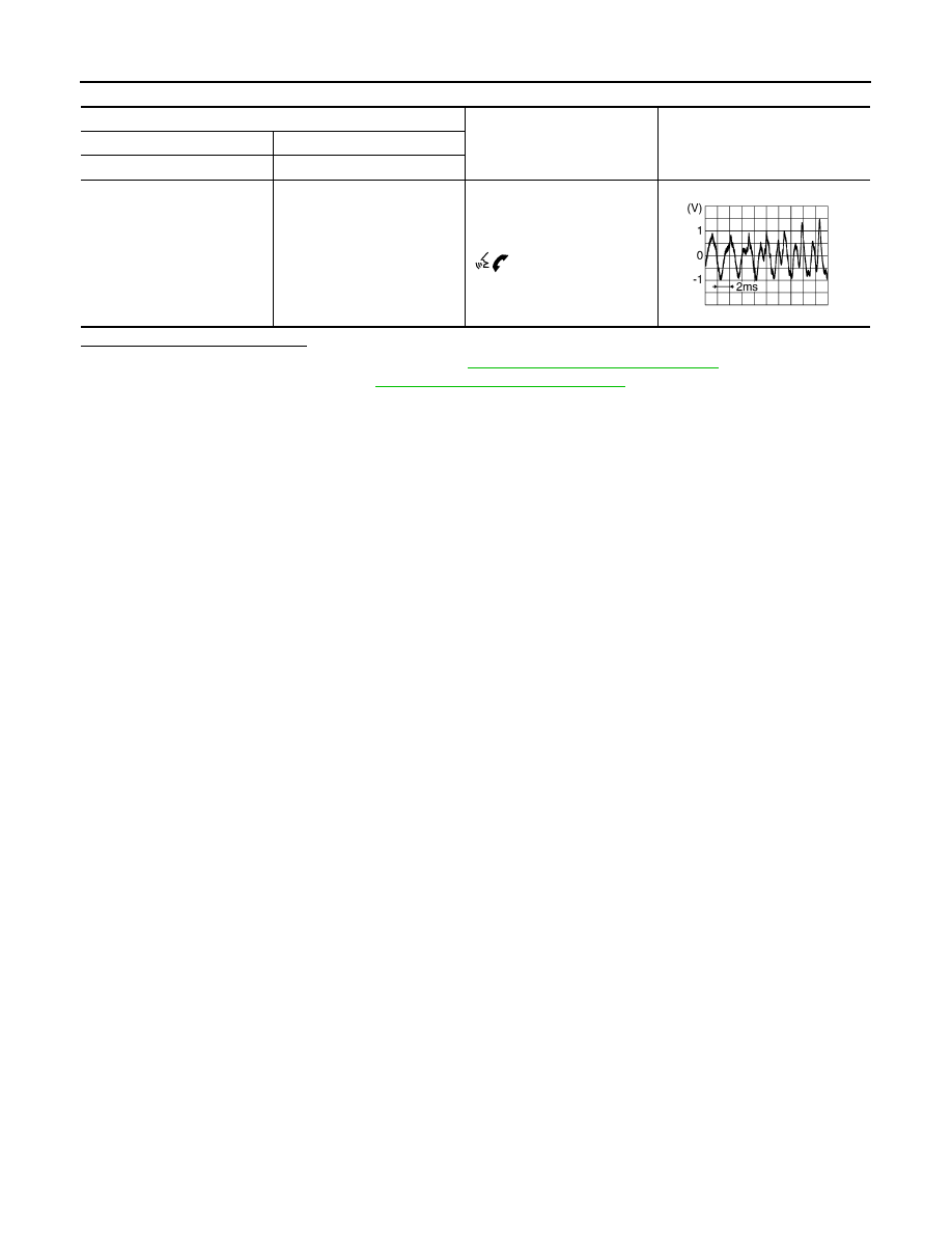
Audio unit connector M40

Condition

Reference value

(+)

(

−)

Terminal

Terminal

25

24

During voice guide output with 

 switch pressed.

SKIB3609E

AV

BLUETOOTH® CONTROL SIGNAL CIRCUIT

AV-105

< DTC/CIRCUIT DIAGNOSIS >

[DISPLAY AUDIO]

C

D

E

F

G

H

I

J

K

L

M

B

A

O

P

BLUETOOTH® CONTROL SIGNAL CIRCUIT

Diagnosis Procedure

INFOID:0000000009681873

Regarding Wiring Diagram information, refer to 

AV-83, "Wiring Diagram"

.

1.

CHECK CONTROL SIGNAL CIRCUIT CONTINUITY

1. Turn ignition switch OFF.
2. Disconnect Bluetooth

®

 control unit connector B33.

3. Check continuity between Bluetooth

®

 control unit connector B33 and ground.

Is the inspection result normal?

YES

>> Replace Bluetooth

®

 control unit. Refer to 

AV-123, "Removal and Installation"

.

NO

>> Repair or replace harness or connectors.

Bluetooth

®

 control unit

Ground

Continuity

Connector

Terminals

B33

20

Yes

22

23

24

27

AV-106

< DTC/CIRCUIT DIAGNOSIS >

[DISPLAY AUDIO]

REAR VIEW CAMERA IMAGE SIGNAL CIRCUIT

REAR VIEW CAMERA IMAGE SIGNAL CIRCUIT

Diagnosis Procedure

INFOID:0000000009681874

Regarding Wiring Diagram information, refer to 

AV-83, "Wiring Diagram"

.

1.

CHECK REVERSE INPUT SIGNAL

1. Turn ignition switch ON.

2. Shift the selector lever to R (reverse).

3. Check voltage between audio unit connector M40 and ground.

Is inspection result normal?

YES

>> GO TO 2.

NO

>> Repair or replace harness or connectors.

2.

CHECK CAMERA POWER SUPPLY CIRCUIT CONTINUITY

1. Turn ignition switch OFF.

2. Disconnect audio unit connector M40 and rear view camera connector.

3. Check continuity between audio unit connector M40 and rear view camera connector D501.

4. Check continuity between audio unit connector M40 and ground.

Is inspection result normal?

YES

>> GO TO 3.

NO

>> Repair or replace harness or connectors.

3.

CHECK CAMERA POWER SUPPLY VOLTAGE

1. Connect audio unit connector M40 and rear view camera connector.

2. Turn ignition switch ON.

3. Shift the selector lever to R (reverse).

4. Check voltage between audio unit connector M40 and ground.

Is inspection result normal?

YES

>> GO TO 4.

NO

>> Replace audio unit. Refer to 

AV-118, "Removal and Installation"

.

Audio unit

Ground

Condition

Voltage

(Approx.)

(+)

(

−)

Connector

Terminal

M40

50

Selector lever in R (re-
verse)

Battery Voltage

Audio unit

Rear view camera

Continuity

Connector

Terminal

Connector

Terminal

M40

34

D501

2

Yes

Audio unit

Ground

Continuity

Connector

Terminal

M40

34

No

Audio unit

Ground

Condition

Voltage

(Approx.)

(+)

(

−)

Connector

Terminal

M40

34

Selector lever is in “R”.

6.0 V

AV

REAR VIEW CAMERA IMAGE SIGNAL CIRCUIT

AV-107

< DTC/CIRCUIT DIAGNOSIS >

[DISPLAY AUDIO]

C

D

E

F

G

H

I

J

K

L

M

B

A

O

P

4.

CHECK CAMERA IMAGE SIGNAL CIRCUIT CONTINUITY

1. Turn ignition switch OFF.

2. Disconnect audio unit connector M40 and rear view camera connector.

3. Check continuity between audio unit connector M40 and rear view camera connector D501.

4. Check continuity between audio unit connector M40 and ground.

Is inspection result normal?

YES

>> GO TO 5.

NO

>> Repair or replace harness or connectors.

5.

CHECK CAMERA GROUND CIRCUIT CONTINUITY

Check continuity between audio unit connector M40 and rear view camera connector D501.

Is inspection result normal?

YES

>> GO TO 6.

NO

>> Repair or replace harness or connectors.

6.

CHECK CAMERA IMAGE SIGNAL

1. Connect audio unit connector M40 and rear view camera connector.

2. Turn ignition switch ON.

3. Shift the selector lever to R (reverse).

4. Check signal between audio unit connector M40 and ground.

Is inspection result normal?

YES

>> Replace audio unit. Refer to 

AV-118, "Removal and Installation"

.

NO

>> Replace rear view camera. Refer to 

AV-122, "Removal and Installation"

.

Audio unit

Rear view camera

Continuity

Connector

Terminal

Connector

Terminal

M40

35

D501

4

Yes

Audio unit

Ground

Continuity

Connector

Terminal

M40

35

No

Audio unit

Rear view camera

Continuity

Connector

Terminal

Connector

Terminal

M40

33

D501

1

Yes

Audio unit

Ground

Condition

Reference value

(+)

(

−)

Connector

Terminal

M40

35

Camera image dis-

played.

SKIB2251J


Content   ..  26  27  28  29   ..