Nissan Versa Sedan. Manual - part 837


  Index      Nissan     Nissan Versa Sedan (2014 year) - Service and Repair Manual


Search            


Content   ..  835  836  837  838   ..


Nissan Versa Sedan. Manual - part 837


TM-254

< SERVICE DATA AND SPECIFICATIONS (SDS) 

[4AT: RE4F03C]

SERVICE DATA AND SPECIFICATIONS (SDS)

SERVICE DATA AND SPECIFICATIONS (SDS)

SERVICE DATA AND SPECIFICATIONS (SDS)

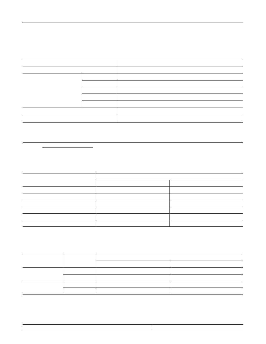
General Specification

INFOID:0000000009268043

*1: Refer to 

MA-12, "Fluids and Lubricants"

.

*2: The fluid capacity is the reference value.

Vehicle Speed at Which Gear Shifting Occurs

INFOID:0000000009268044

Unit: km/h (MPH)

• At half throttle, the accelerator opening is 4/8 of the full opening.

Vehicle Speed at Which Lock-up Occurs/Releases

INFOID:0000000009268045

Unit: km/h (MPH)

• At closed throttle, the accelerator opening is less than 1/8 condition. (Closed throttle position signal OFF)
• At half throttle, the accelerator opening is 4/8 of the full opening.

Stall Speed

INFOID:0000000009268046

Transaxle model

RE4F03C

Stall torque ratio

1.91 : 1

Transmission gear ratio

1st

2.861

2nd

1.562

3rd

1.000

4th

0.697

Reverse

2.310

Recommended fluid

Genuine NISSAN Matic S ATF

*1

Fluid capacity

5.2 liter (5-1/2 US qt, 4-5/8 Imp qt)

*2

CAUTION:

• Use only Genuine NISSAN Matic S ATF. Do not mix with other ATF.
• Using ATF other than Genuine NISSAN Matic S ATF will cause deterioration of driveability and A/T durability, and may dam-

age the A/T, which is not covered by the warranty.

Gear position

Throttle position

Full throttle 

Half throttle 

D

→ D

2

52 – 58 (33 – 36)

28 – 34 (18 – 21)

D

→ D

3

98 – 104 (61 – 64)

56 – 62 (35 – 38)

D

→ D

4

 155 – 161 (97 – 100)

 122 – 128 (76 – 79)

D

→ D

3

 150 – 156 (94 – 96)

 63 – 69 (40 – 42)

D

→ D

2

 88 – 94 (55 – 58)

 39 – 45 (25 – 27)

D

→ D

1

38 – 44 (24 – 27)

17 – 23 (11 – 14)

Throttle position

Gear position

Vehicle speed

Lock-up ON

Lock-up OFF

Closed throttle

3GR

33 – 39 (21 – 24)

30 – 36 (19 – 22)

4GR

52 – 58 (33 – 36)

48 – 54 (30 – 33)

Half throttle

3GR (OD OFF)

87 – 93 (55 – 57)

84 – 90 (53 – 55)

4GR

122 – 128 (76 – 79)

92 – 98 (58 – 60)

Stall speed

2,410 – 2,850 rpm

SERVICE DATA AND SPECIFICATIONS (SDS)

TM-255

< SERVICE DATA AND SPECIFICATIONS (SDS) 

[4AT: RE4F03C]

C

E

F

G

H

I

J

K

L

M

A

B

TM

N

O

P

Line Pressure

INFOID:0000000009268047

Unit: kPa (kg/cm2, psi)

Torque Converter

INFOID:0000000009268048

Select position

Engine speed

Line pressure

“R” position

Idle speed

570 (5.81, 82.7)

Stall speed

2,140 (21.83, 310.3)

“D” position

Idle speed

410 (4.18, 59.5)

Stall speed

1,400 (14.28, 203.0)

Dimension between end of converter housing and torque converter

16.2 mm (0.638 in)

TM-256

< PRECAUTION >

[CVT: RE0F11A]

PRECAUTIONS

PRECAUTION

PRECAUTIONS

Precaution for Supplemental Restraint System (SRS) "AIR BAG" and "SEAT BELT 
PRE-TENSIONER"

INFOID:0000000009268049

The Supplemental Restraint System such as “AIR BAG” and “SEAT BELT PRE-TENSIONER”, used along

with a front seat belt, helps to reduce the risk or severity of injury to the driver and front passenger for certain

types of collision. This system includes seat belt switch inputs and dual stage front air bag modules. The SRS

system uses the seat belt switches to determine the front air bag deployment, and may only deploy one front

air bag, depending on the severity of a collision and whether the front occupants are belted or unbelted.

Information necessary to service the system safely is included in the SR and SB section of this Service Man-

ual.

WARNING:

• To avoid rendering the SRS inoperative, which could increase the risk of personal injury or death in

the event of a collision which would result in air bag inflation, all maintenance must be performed by

an authorized NISSAN/INFINITI dealer.

• Improper maintenance, including incorrect removal and installation of the SRS, can lead to personal

injury caused by unintentional activation of the system. For removal of Spiral Cable and Air Bag

Module, see the SR section.

• Do not use electrical test equipment on any circuit related to the SRS unless instructed to in this

Service Manual. SRS wiring harnesses can be identified by yellow and/or orange harnesses or har-

ness connectors.

PRECAUTIONS WHEN USING POWER TOOLS (AIR OR ELECTRIC) AND HAMMERS

WARNING:

• When working near the Airbag Diagnosis Sensor Unit or other Airbag System sensors with the Igni-

tion ON or engine running, DO NOT use air or electric power tools or strike near the sensor(s) with a

hammer. Heavy vibration could activate the sensor(s) and deploy the air bag(s), possibly causing

serious injury.

• When using air or electric power tools or hammers, always switch the Ignition OFF, disconnect the

battery, and wait at least 3 minutes before performing any service.

Precaution for Procedure without Cowl Top Cover

INFOID:0000000009268050

When performing the procedure after removing cowl top cover, cover

the lower end of windshield with urethane, etc to prevent damage to

windshield.

Precaution for TCM and Transaxle Assembly Replacement

INFOID:0000000009268051

CAUTION:

• To replace TCM, refer to 

TM-325, "Description"

.

• To replace transaxle assembly, refer to 

TM-326, "Description"

.

Precaution for G Sensor Removal/Installation or Replacement

INFOID:0000000009268052

CAUTION:

To remove/install or replace G sensor, refer to 

TM-328, "Description"

.

PIIB3706J

PRECAUTIONS

TM-257

< PRECAUTION >

[CVT: RE0F11A]

C

E

F

G

H

I

J

K

L

M

A

B

TM

N

O

P

General Precautions

INFOID:0000000009268053

• Turn ignition switch OFF and disconnect the battery cable

from the negative terminal before connecting or disconnect-

ing the CVT assembly harness connector. Because battery

voltage is applied to TCM even if ignition switch is turned

OFF.

• When connecting or disconnecting pin connectors into or

from TCM, do not damage pin terminals (bend or break).

Check that there are not any bends or breaks on TCM pin ter-

minal, when connecting pin connectors.

• Perform TCM input/output signal inspection and check

whether TCM functions normally or not before replacing TCM.

Refer to 

TM-299, "Reference Value"

.

• Perform “DTC (Diagnostic Trouble Code) CONFIRMATION

PROCEDURE”.

If the repair is completed DTC should not be displayed in the

“DTC CONFIRMATION PROCEDURE”.

• Always use the specified brand of CVT fluid. Refer to 

MA-12, "Fluids and Lubricants"

.

• Use lint-free paper not cloth rags during work.

• Dispose of the waste oil using the methods prescribed by law, ordinance, etc. after replacing the CVT fluid.

On Board Diagnosis (OBD) System of CVT and Engine

INFOID:0000000009268054

The ECM has an on board diagnostic system. It will light up the malfunction indicator lamp (MIL) to warn the

driver of a malfunction causing emission deterioration.

SEF289H

AAT470A

MEF040DA

JSBIA1315ZZ


Content   ..  835  836  837  838   ..