Nissan Versa Sedan. Manual - part 791


  Index      Nissan     Nissan Versa Sedan (2014 year) - Service and Repair Manual


Search            


Content   ..  789  790  791  792   ..


Nissan Versa Sedan. Manual - part 791


TM-70

< SYSTEM DESCRIPTION >

[4AT: RE4F03C]

COMPONENT PARTS

A/T SHIFT LOCK SYSTEM
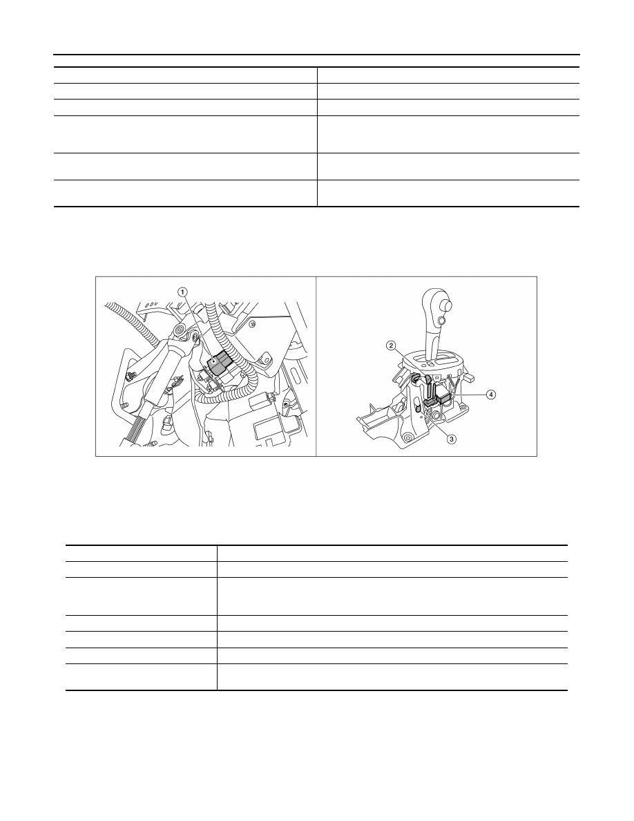
A/T SHIFT LOCK SYSTEM : Component Parts Location

INFOID:0000000009267837

A/T SHIFT LOCK SYSTEM : Component Description

INFOID:0000000009267838

Condition (status)

O/D OFF indicator lamp

Ignition switch OFF.

OFF

Ignition switch ON.

ON (Approx. 2 seconds)

Overdrive control switch is pressed when the selector lever is in 
the “D” position and the O/D OFF indicator lamp is OFF (when sys-
tem is normal).

ON

Overdrive control switch is pressed when the selector lever is in 
the “D” position and the O/D OFF indicator lamp is ON.

OFF

Selector lever is shifted from the “D” position to another position 
when the O/D OFF indicator lamp is ON.

OFF

1

Stop lamp switch.

2

Shift lock release lever.

3

Park position switch.

4

Shift lock solenoid.

ALDIA0267ZZ

Component

Function

Shift lock solenoid

It operates according to the signal from the stop lamp switch and moves the lock lever.

Lock lever

• Rotates according to shift lock solenoid activation and releases the shift lock.
• If shift lock solenoid does not activate, lock lever can be rotated when shift lock release 

button is pressed and shift lock is released.

Detent rod

It links with the selector button and restricts the selector lever movement.

Park position switch

It detects that the selector lever is in “P” position.

Shift lock release button

Forcibly releases the shift lock when pressed.

Stop lamp switch

• The stop lamp switch turns ON when the brake pedal is depressed.
• When the stop lamp switch turns ON, the shift lock solenoid is energized.

STRUCTURE AND OPERATION

TM-71

< SYSTEM DESCRIPTION >

[4AT: RE4F03C]

C

E

F

G

H

I

J

K

L

M

A

B

TM

N

O

P

STRUCTURE AND OPERATION

TRANSAXLE
TRANSAXLE : Cross-Sectional View

INFOID:0000000009267839

1.

Converter housing

2.

Oil pump

3.

Low clutch

4.

Rear planetary gear

5.

Low & reverse brake

6.

Front planetary gear

7.

Low one-way clutch

8.

High clutch

9.

Reverse clutch

10. 2-4 brake band (Brake band)

11. Band servo piston

12. Side cover

13. Output gear

14. Idler gear 

15. Transaxle case

16. Reduction pinion gear

17. Final gear

18. Differential case

19. Input shaft

20. Torque converter

JSDIA1625ZZ

TM-72

< SYSTEM DESCRIPTION >

[4AT: RE4F03C]

STRUCTURE AND OPERATION

TRANSAXLE : System Diagram

INFOID:0000000009267840

TRANSAXLE : System Description

INFOID:0000000009267841

DESCRIPTION

With the use of 2 sets of planetary gears, A/T enables 4-speed transmission for forward and 1-speed transmis-

sion for backward, depending on the combination of 3 sets of multiple-disc clutches, a set of multiple-disc

brakes, a set of one-way clutches and a set of brake bands.

CLUTCH/BRAKE AND BAND CHART

×: Operated

*: Operates during “progressive” acceleration.

P POSITION (PARKING MECHANISM)

When the selector lever is shifted to the “P” position, the parking pole engages with the parking gear (inte-

grated with the idler gear), fixing the output shaft in place.

JSDIA1992GB

Shift position

Clutch/brake

L/C

L&R/B

2-4

/B

(B/B)

H/C

R/C

OWC

P

R

×

×

N

D

1GR

×

×*

2GR

×

×

3GR

×

×

4GR

×

×

2

×

×*

1

×

×

STRUCTURE AND OPERATION

TM-73

< SYSTEM DESCRIPTION >

[4AT: RE4F03C]

C

E

F

G

H

I

J

K

L

M

A

B

TM

N

O

P

TRACTION TRANSMISSION OF EACH RANGE

“P” position, “N” position

The drive force from the input shaft is not transmitted because all clutches and bands are released.

“1” position, “D

1”

 position

JSDIA1993GB

JSDIA1994GB


Content   ..  789  790  791  792   ..