Nissan Versa Sedan. Manual - part 706


  Index      Nissan     Nissan Versa Sedan (2014 year) - Service and Repair Manual


Search            


Content   ..  704  705  706  707   ..


Nissan Versa Sedan. Manual - part 706


SEC-96

< DTC/CIRCUIT DIAGNOSIS >

[WITH INTELLIGENT KEY SYSTEM]

B210E STARTER RELAY

2. Disconnect BCM connector.

3. Disconnect starter relay.

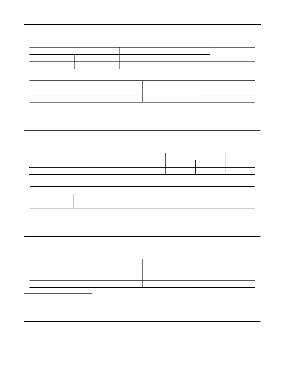
4. Check continuity between BCM harness connector and starter relay harness connector.

5. Check continuity between BCM harness connector and ground.

Is the inspection result normal?

YES

>> GO TO 3.

NO

>> Repair or replace harness.

3.

CHECK STARTER RELAY CIRCUIT 1

1. Turn ignition switch OFF.

2. Disconnect IPDM E/R connector.

3. Check continuity between IPDM E/R harness connector and starter relay harness connector.

4. Check continuity between BCM harness connector and ground.

Is the inspection result normal?

YES

>> GO TO 6.

NO

>> Repair or replace harness.

4.

CHECK STARTER RELAY POWER SUPPLY CIRCUIT

1. Turn ignition switch OFF.

2. Disconnect starter relay.

3. Check voltage between starter relay harness connector and ground.

Is the inspection result normal?

YES

>> GO TO 5.

NO-1 >> Check 40 A fusible link [Figure H, located in the fuse block (J/B)].

NO-2 >> Check harness for open or short between starter relay and fusible link.

5.

CHECK STARTER RELAY CIRCUIT 2

1. Disconnect IPDM E/R connector.

2. Check continuity between IPDM E/R harness connector and starter relay harness connector.

BCM

Starter relay

Continuity

Connector

Terminal

Connector

Terminal

M98

97

E41

1

Yes

BCM

Ground

Continuity

Connector

Terminal

M98

97

No

IPDM E/R

Starter relay

Continuity

Connector

Terminal

Connector

Terminal

E44

15

E41

2

Yes

IPDM E/R

Ground

Continuity

Connector

Terminal

E44

15

No

(+)

(–)

Voltage (V)

(Approx.)

Starter relay

Connector

Terminal

E41

5

Ground

Battery voltage

B210E STARTER RELAY

SEC-97

< DTC/CIRCUIT DIAGNOSIS >

[WITH INTELLIGENT KEY SYSTEM]

C

D

E

F

G

H

I

J

L

M

A

B

SEC

N

O

P

3. Check continuity between BCM harness connector and ground.

Is the inspection result normal?

YES

>> GO TO 6.

NO

>> Repair or replace harness.

6.

CHECK STARTER RELAY

Refer to 

SEC-97, "Component Inspection"

.

Is the inspection result normal?

YES

>> GO TO 7.

NO

>> Replace starter relay.

7.

REPLACE BCM

1. Replace BCM. Refer to 

BCS-69, "Removal and Installation"

.

2. Perform initialization of BCM and registration of all Intelligent keys using CONSULT.

3. Perform DTC CONFIRMATION PROCEDURE for DTC B210E. Refer to 

SEC-95, "DTC Logic"

.

Is the inspection result normal?

YES

>> Inspection End.

NO

>> Replace IPDM E/R. Refer to 

PCS-30, "Removal and Installation"

.

Component Inspection

INFOID:0000000009268447

1.

CHECK STARTER RELAY

1. Turn ignition switch OFF.

2. Disconnect starter relay.

3. Check continuity between starter relay terminals.

Is the inspection result normal?

YES

>> Inspection End.

NO

>> Replace starter relay.

IPDM E/R

Starter relay

Continuity

Connector

Terminal

Connector

Terminal

E43

3

E41

3

Yes

IPDM E/R

Ground

Continuity

Connector

Terminal

E43

3

No

Starter relay

Condition

Continuity

Terminal

3

5

12 V direct current supply between terminals 1 and 2

Yes

No current supply

No

SEC-98

< DTC/CIRCUIT DIAGNOSIS >

[WITH INTELLIGENT KEY SYSTEM]

B210F SHIFT POSITION/CLUTCH INTERLOCK SWITCH

B210F SHIFT POSITION/CLUTCH INTERLOCK SWITCH

DTC Logic

INFOID:0000000009268448

DTC DETECTION LOGIC

NOTE:

If DTC B210F is displayed with DTC U1000, first perform the trouble diagnosis for DTC U1000. Refer to 

BCS-

59, "DTC Logic"

.

DTC CONFIRMATION PROCEDURE

1.

PERFORM DTC CONFIRMATION PROCEDURE

1. Shift selector lever to the P position.

2. Turn ignition switch ON and wait 1 second or more.

3. Shift selector lever to the N position and wait 1 second or more.

4. Shift selector lever to the position other than P and N, and wait 1 second or more.

5. Check DTC in Self Diagnostic Result mode of IPDM E/R using CONSULT.
Is DTC detected?

YES

>> Go to 

SEC-98, "Diagnosis Procedure"

.

NO

>> Inspection End.

Diagnosis Procedure 

INFOID:0000000009268449

Regarding Wiring Diagram information, refer to 

SEC-27, "Wiring Diagram"

.

1.

CHECK DTC OF BCM

Check DTC in Self Diagnostic Result mode of BCM using CONSULT.
Is DTC detected?

YES

>> Perform the trouble diagnosis related to the detected DTC. Refer to 

BCS-48, "DTC Index"

.

NO

>> GO TO 2.

2.

CHECK IPDM E/R SIGNAL CIRCUIT OPEN AND SHORT

1. Turn ignition switch OFF.

2. Disconnect IPDM E/R connector.

3. Disconnect transmission range switch connector.

4. Check continuity between IPDM E/R harness connector and transmission range switch harness connec-

tor.

5. Check continuity between IPDM E/R harness connector and ground.

DTC No.

Trouble diagnosis name

DTC detecting condition

Possible cause

B210F

INTRLCK/PNP SW ON

IPDM E/R detects a difference between the 
following signals
• P/N position signal from transmission 

range switch and P/N position signal 
(CAN) from BCM 

• Harness or connectors

(The CAN communication line is open 
or shorted.)

• Harness or connectors

(Transmission range switch circuit is 
open or shorted.)

• Transmission range switch
• IPDM  E/R
• BCM

IPDM E/R

Transmission range switch

Continuity

Connector

Terminal

Connector

Terminal

E45

21

F52

1

Yes

B210F SHIFT POSITION/CLUTCH INTERLOCK SWITCH

SEC-99

< DTC/CIRCUIT DIAGNOSIS >

[WITH INTELLIGENT KEY SYSTEM]

C

D

E

F

G

H

I

J

L

M

A

B

SEC

N

O

P

Is the inspection result normal?

YES

>> Replace IPDM E/R. Refer to 

PCS-30, "Removal and Installation"

.

NO

>> Repair or replace harness.

(+)

(–)

Continuity

IPDM E/R

Connector

Terminal

E45

21

Ground

No


Content   ..  704  705  706  707   ..