Nissan Versa Sedan. Manual - part 612


  Index      Nissan     Nissan Versa Sedan (2014 year) - Service and Repair Manual


Search            


Content   ..  610  611  612  613   ..


Nissan Versa Sedan. Manual - part 612


PCS-34

< SYSTEM DESCRIPTION >

[IPDM E/R (WITHOUT I-KEY)]

SYSTEM

RELAY CONTROL SYSTEM : System Description

INFOID:0000000009266432

IPDM E/R activates the internal control circuit to perform the relay ON-OFF control according to the input sig-

nals from various sensors and the request signals received from control units via CAN communication.

CAUTION:

To prevent damage to the parts, IPDM E/R integrated relays cannot be removed.

POWER CONSUMPTION CONTROL SYSTEM
POWER CONSUMPTION CONTROL SYSTEM : System Diagram

INFOID:0000000009266433

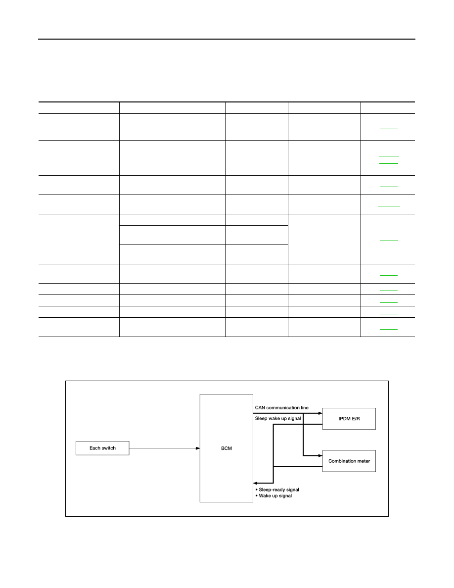
POWER CONSUMPTION CONTROL SYSTEM : System Description

INFOID:0000000009266434

OUTLINE

• IPDM E/R incorporates a power consumption control function that reduces the power consumption accord-

ing to the vehicle status. 

Control relay

Input/output

Transmit unit

Control part

Reference page

• Headlamp high relay
• Headlamp low relay

• High beam request signal
• Low beam request signal

BCM (CAN)

• Headlamp high
• Headlamp low
• Daytime light relay 2

EXL-8

Tail lamp relay

Position light request signal

BCM (CAN)

• Parking  lamp
• License plate lamp
• Tail  lamp
• Illumination system

EXL-11

INL-10

• Front wiper relay
• Front wiper high relay

Front wiper request signal

BCM (CAN)

Front wiper motor

WW-6

A/C relay

A/C request signal

• BCM  (CAN)
• ECM  (CAN)

A/C compressor
(Magnet clutch)

HAC-10

Starter control relay

Starter control relay signal

BCM (CAN)

Starter motor

STR-8

Transmission range switch signal 
(CVT models)

Transmission range 
switch

Clutch interlock switch signal (M/T 
models)

Clutch interlock 
switch

• Cooling fan low relay
• Cooling fan high relay

Cooling fan request signal

ECM (CAN)

Cooling fan motor (low)
Cooling fan motor (high)

EC-39

ECM relay

ECM relay control signal

ECM (CAN)

ECM

EC-30

Throttle control motor relay Throttle control motor control signal

ECM (CAN)

ECM

EC-30

Fuel pump relay

Fuel pump request signal

ECM (CAN)

Fuel pump

EC-33

Ignition relay

Ignition switch ON or START signal

Ignition switch

Ignition switch ON or 
START power 

EC-36

ALCIA0030GB

PCS

SYSTEM

PCS-35

< SYSTEM DESCRIPTION >

[IPDM E/R (WITHOUT I-KEY)]

C

D

E

F

G

H

I

J

K

L

B

A

O

P

N

• IPDM E/R changes its status (control mode) with the sleep wake up signal received from BCM via CAN com-

munication.

Normal mode (wake-up)

- CAN communication is normally performed with other control units.

- Individual unit control by IPDM E/R is normally performed.

Low power consumption mode (sleep)

- Low power consumption control is active.

- CAN transmission is stopped.

SLEEP MODE ACTIVATION

• IPDM E/R judges that the sleep-ready conditions are fulfilled when the ignition switch is OFF and none of the

conditions below are present. Then it transmits a sleep-ready signal (ready) to BCM via CAN communica-

tion.

- Outputting signals to actuators

- Switches or relays operating

- Output requests are being received from control units via CAN communication.

• IPDM E/R stops CAN communication and enters the low power consumption mode when it receives a sleep

wake up signal (sleep) from BCM and the sleep-ready conditions are fulfilled.

WAKE-UP OPERATION

• IPDM E/R changes from the low power consumption mode to the normal mode when it receives a sleep

wake-up signal (wake up) from BCM or any of the following conditions is fulfilled. In addition, it transmits a

sleep-ready signal (not-ready) to BCM via CAN communication to report the CAN communication start.

- Ignition switch ON

- An output request is received from a control unit via CAN communication.

PCS-36

< SYSTEM DESCRIPTION >

[IPDM E/R (WITHOUT I-KEY)]

DIAGNOSIS SYSTEM (IPDM E/R)

DIAGNOSIS SYSTEM (IPDM E/R)

Diagnosis Description

INFOID:0000000009266435

AUTO ACTIVE TEST

Description

In auto active test, the IPDM E/R sends a drive signal to the following systems to check their operation.

• Front wiper (LO, HI)

• Parking lamp

• License plate lamp

• Tail lamp

• Front fog lamp

• Headlamp (LO, HI)

• A/C compressor (magnet clutch)

• Cooling fan

Operation Procedure

NOTE:

Never perform auto active test in the following conditions.

• Passenger door is open

• CONSULT is connected
1. Close the hood and lift the wiper arms from the windshield. (Prevent windshield damage due to wiper

operation)

NOTE:

When auto active test is performed with hood opened, sprinkle water on windshield beforehand.

2. Turn the ignition switch OFF.
3. Turn the ignition switch ON, and within 20 seconds, press the driver door switch 10 times. Then turn the

ignition switch OFF.

4. Turn the ignition switch ON within 10 seconds. After that the horn sounds once and the auto active test

starts.

5. After a series of the following operations is repeated 3 times, auto active test is completed.
NOTE:

• When auto active test has to be cancelled halfway through test, turn the ignition switch OFF.

• When auto active test is not activated, door switch may be the cause. Check door switch. Refer to 

DLK-235,

"Component Function Check"

.

Inspection in Auto Active Test

When auto active test is actuated, the following operation sequence is repeated 3 times.

Operation se-

quence

Inspection location

Operation

1

Front wiper

LO for 5 seconds 

→ HI for 5 seconds

2

• Parking  lamp
• License plate lamp
• Tail lamp
• Front fog lamp

10 seconds

3

Headlamp

LO for 10 seconds 

→HI ON ⇔ OFF 5 times

4

A/C compressor (magnet clutch)

ON 

⇔ OFF 5 times

5

Cooling fan

LO for 5 seconds 

→ MID for 3 seconds → HI for 2 seconds

PCS

DIAGNOSIS SYSTEM (IPDM E/R)

PCS-37

< SYSTEM DESCRIPTION >

[IPDM E/R (WITHOUT I-KEY)]

C

D

E

F

G

H

I

J

K

L

B

A

O

P

N

Concept of Auto Active Test

• IPDM E/R starts the auto active test with the door switch signals transmitted by BCM via CAN communica-

tion. Therefore, the CAN communication line between IPDM E/R and BCM is considered normal if the auto

active test starts successfully.

• The auto active test facilitates troubleshooting if any systems controlled by IPDM E/R cannot be operated.

Diagnosis Chart in Auto Active Test

CONSULT Function (IPDM E/R)

INFOID:0000000009266436

APPLICATION ITEM

CONSULT performs the following functions via CAN communication with IPDM E/R.

JMMIA0812GB

Symptom

Inspection contents

Possible cause

Any of the following components do not operate

• Parking  lamp
• License plate lamp
• Tail  lamp
• Front  fog  lamp
• Headlamp (HI, LO)
• Front wiper (HI, LO)

Perform auto active test.
Does the applicable system op-
erate?

YES

BCM signal input circuit

NO

• Lamp or motor
• Lamp or motor ground circuit
• Harness or connector between 

IPDM E/R and applicable system

• IPDM  E/R

A/C compressor does not operate

Perform auto active test.
Does the magnet clutch oper-
ate?

YES

• BCM signal input circuit
• CAN communication signal be-

tween BCM and ECM

• CAN communication signal be-

tween ECM and IPDM E/R

NO

• Magnet clutch
• Harness or connector between 

IPDM E/R and magnet clutch

• IPDM  E/R

Cooling fan does not operate

Perform auto active test.
Does the cooling fan operate?

YES

• ECM signal input circuit
• CAN communication signal be-

tween ECM and IPDM E/R

NO

• Cooling fan motor
• Harness or connector between 

IPDM E/R and cooling fan motor

• IPDM  E/R

Direct Diagnostic Mode

Description

Ecu Identification

The IPDM E/R part number is displayed.

Self Diagnostic Result

The IPDM E/R self diagnostic results are displayed.

Data Monitor

The IPDM E/R input/output data is displayed in real time.


Content   ..  610  611  612  613   ..