Nissan Versa Sedan. Manual - part 603
PB-6
< REMOVAL AND INSTALLATION >
PARKING BRAKE CONTROL
REMOVAL AND INSTALLATION
PARKING BRAKE CONTROL
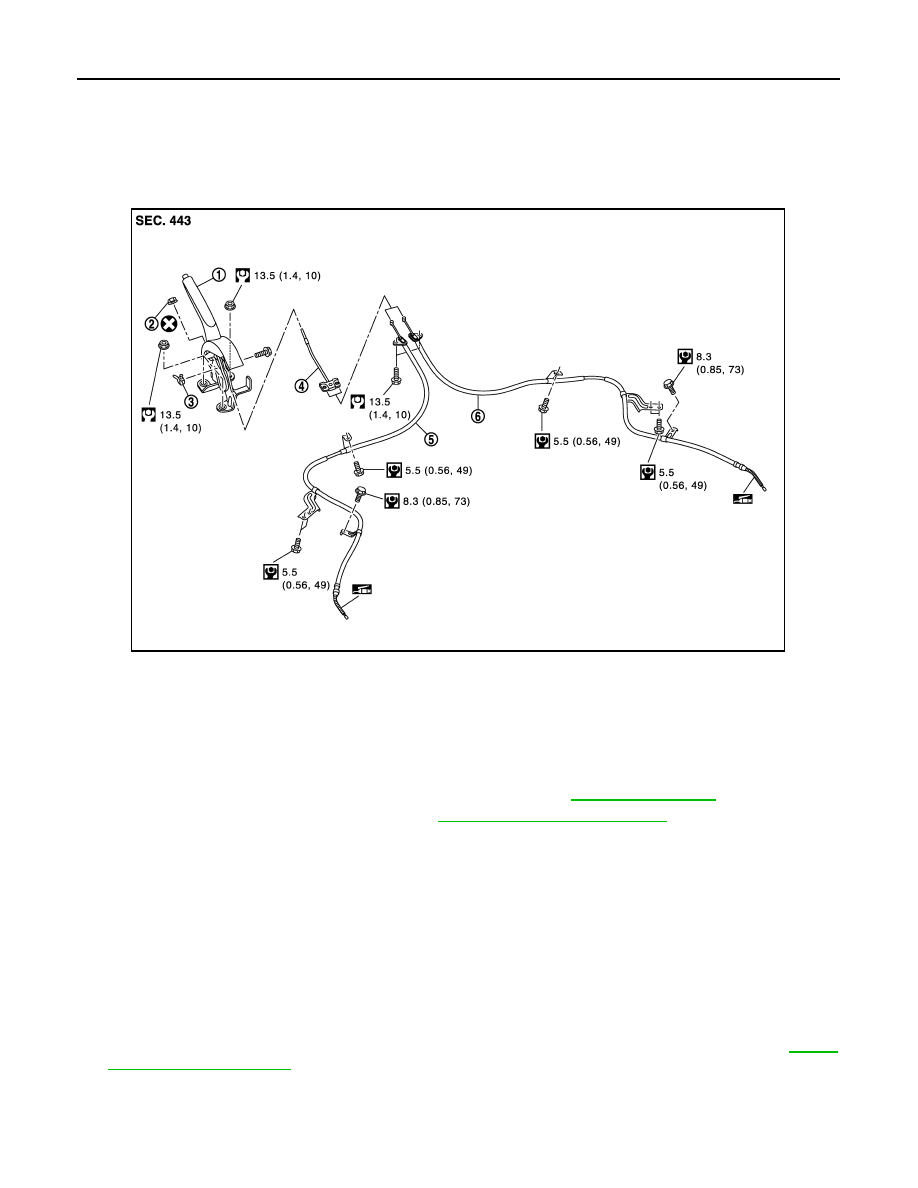
Exploded View
INFOID:0000000009266939
Removal and Installation
INFOID:0000000009266940
REMOVAL
1. Remove rear wheel and tire assemblies using power tool. Refer to
.
2. Remove the center console assembly. Refer to
IP-23, "Removal and Installation"
3. Disconnect the harness connector from the parking brake switch.
4. Remove and discard the adjusting nut to loosen the front cable.
CAUTION:
Do not reuse the adjusting nut.
5. Separate both rear cables from the front cable.
6. Remove the parking brake lever assembly and front cable.
7. Remove the front cable from parking brake lever assembly.
8. Remove the parking brake switch from parking brake lever assembly.
9. Remove both rear cables from the toggle lever.
10. Remove the center floor insulator to gain access to the rear cable bolts.
11. Remove the brake shoes and disconnect the rear cables from the toggle levers. Refer to
12. Disconnect and remove the rear cables from each backing plate.
INSTALLATION
Installation is in the reverse order of the removal.
1.
Parking brake lever assembly
2.
Adjusting nut
3.
Parking brake switch
4.
Front cable
5.
Rear cable (LH)
6.
Rear cable (RH)
JPFIB0133GB