Nissan Versa Sedan. Manual - part 374
EXHAUST MANIFOLD
EM-31
< REMOVAL AND INSTALLATION >
[HR16DE]
C
D
E
F
G
H
I
J
K
L
M
A
EM
N
P
O
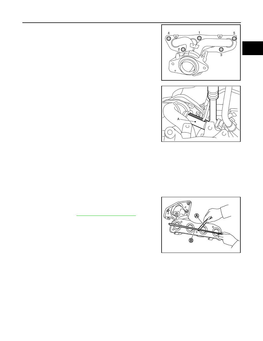
• Loosen nuts in reverse order as shown.
8. Use Tool (A) to remove the air-fuel ratio sensor 1 (if necessary).
CAUTION:
• Handle the air-fuel ratio sensor carefully and avoid
impacts.
• Before installing a new air-fuel ratio sensor 1, clean the
exhaust tube threads using suitable tool and approved
anti-seize lubricant.
• If air-fuel ratio sensor is dropped onto a hard surface,
such as a concrete floor, from a height of 0.5 m or more,
discard the sensor and use a new one.
9. Remove exhaust manifold gasket and discard.
10. Remove stud bolt using suitable tool from cylinder head (if necessary).
INSPECTION AFTER REMOVAL
Mounting Surface Distortion
• Using suitable tools (A) and (B), check the surface distortion of the
exhaust manifold mating surface as shown.
• Replace exhaust manifold if it exceeds the limit.
INSTALLATION
Installation is in the reverse order of removal. Note the following:
Exhaust manifold
JPBIA4127ZZ
Tool number
: KV10117100 ( — )
Oxygen sensor thread cleaner
: — (J-43897-12)
Oxygen sensor thread cleaner
: — (J-43897-18)
JPBIA4126ZZ
Limit
: Refer to
.
PBIC3530J