Nissan Rogue. Manual - part 702
EVAP CANISTER FILTER
FL-23
< REMOVAL AND INSTALLATION >
C
D
E
F
G
H
I
J
K
L
M
A
FL
N
P
O
EVAP CANISTER FILTER
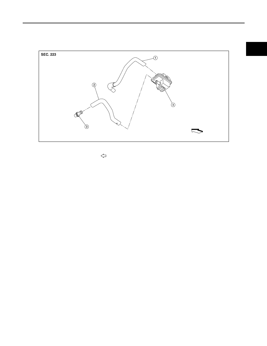
Exploded View
INFOID:0000000011279629
Removal and Installation
INFOID:0000000011279630
REMOVAL
1. Disconnect EVAP canister vent control valve hose from EVAP canister filter.
2. Disconnect canister drain hose from EVAP canister filter.
3. Remove the bolt and the EVAP canister filter.
INSTALLATION
Installation is in the reverse order of removal.
ALBIA1199ZZ
1.
EVAP canister vent control valve hose
2.
Canister drain hose
3.
Plug
4.
EVAP canister filter
Front