Nissan Rogue. Manual - part 680
FRONT DRIVE SHAFT BOOT
FAX-13
< REMOVAL AND INSTALLATION >
[FWD]
C
E
F
G
H
I
J
K
L
M
A
B
FAX
N
O
P
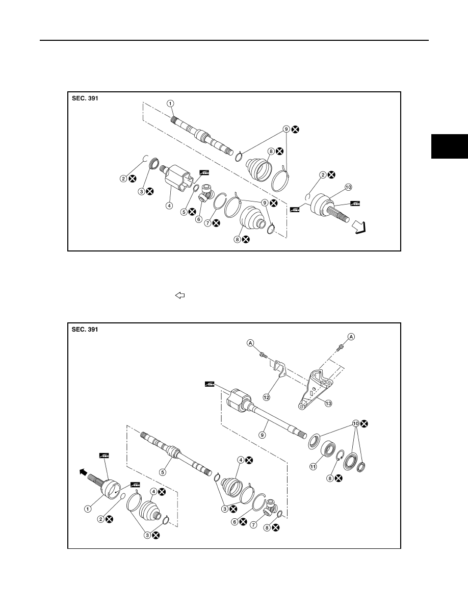
FRONT DRIVE SHAFT BOOT
Exploded View
INFOID:0000000011278625
(LH)
(RH)
AWDIA1161ZZ
1.
Shaft
2.
Circular clip
3.
Dust shield
4.
Housing
5.
Snap ring
6.
Spider assembly
7.
Stopper ring
8.
Boot
9.
Boot band
10. Joint sub-assembly
Wheel side
AWDIA1200ZZ
1.
Joint sub-assembly
2.
Circular clip
3.
Boot band
4.
Boot
5.
Shaft
6.
Stopper ring