Nissan Rogue. Manual - part 1262


  Index      Nissan     Nissan Rogue (2015 year) - Service and Repair Manual


Search            


Content   ..  1260  1261  1262  1263   ..


Nissan Rogue. Manual - part 1262


FRONT WIPER DOES NOT OPERATE

WW-51

< SYMPTOM DIAGNOSIS >

C

D

E

F

G

H

I

J

K

M

A

B

WW

N

O

P

FRONT WIPER DOES NOT OPERATE

Description

INFOID:0000000011280407

The front wiper does not operate under any operation conditions.

Diagnosis Procedure

INFOID:0000000011280408

Regarding Wiring Diagram information, refer to 

WW-20, "Wiring Diagram"

.

1.

 CHECK WIPER RELAY OPERATION

CONSULT ACTIVE TEST

1. Select “FR WIPER” in “Active Test” of “BCM (WIPER)”.

2. Check front wiper operation.

Is the inspection result normal?

YES

>>  GO TO 5.

NO

>> GO TO 2.

2.

 CHECK FRONT WIPER MOTOR FUSE

Refer to 

WW-33, "Diagnosis Procedure"

.

Is the fuse blown?

YES

>> Replace the blown fuse after repairing the affected circuit.

NO

>> GO TO 3.

3.

 CHECK FRONT WIPER MOTOR GROUND CIRCUIT 

Refer to 

WW-40, "Diagnosis Procedure"

.

Is the inspection result normal?

YES

>> GO TO 4.

NO

>> Repair or replace harness.

4.

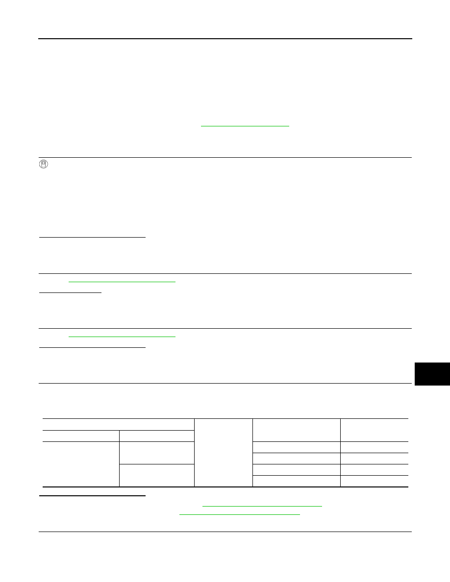
 CHECK FRONT WIPER MOTOR OUTPUT VOLTAGE

1. Turn the ignition switch ON.

2. Select “FRONT WIPER” in “Active Test” of “IPDM E/R” with CONSULT.

3. Check voltage between IPDM E/R harness connector and ground while wipers are operating.

Is the inspection result normal?

YES

>> Replace front wiper motor. Refer to 

WW-69, "Removal and Installation"

.

NO

>> Replace IPDM E/R. Refer to 

PCS-40, "Removal and Installation"

.

5.

 CHECK FRONT WIPER REQUEST SIGNAL INPUT

1. Select “FR WIP REQ” in “Data Monitor” of “IPDM E/R” with CONSULT.

2. Switch the front wiper switch to HI and LO.

3. Check the status of FR WIP REQ while operating the switch.

LO

: Front wiper LO operation

HI

: Front wiper HI operation

OFF

: Front wiper stop

IPDM E/R

Ground

FRONT WIPER

Voltage

(Approx.)

Connector

Terminal

E121

48

LO

Battery voltage

OFF

0 V

45

HI

Battery voltage

OFF

0 V

WW-52

< SYMPTOM DIAGNOSIS >

FRONT WIPER DOES NOT OPERATE

Is the inspection result normal?

YES

>> Replace IPDM E/R. Refer to 

PCS-40, "Removal and Installation"

 .

NO

>> GO TO 6.

6.

 CHECK COMBINATION SWITCH (WIPER AND WASHER SWITCH)

Check combination switch (wiper and washer switch). Refer to 

WW-43, "Component Inspection"

.

Is the inspection result normal?

YES

>> Replace BCM. Refer to 

BCS-75, "Removal and Installation"

 (with Intelligent Key system) or 

BCS-

135, "Removal and Installation"

 (without Intelligent Key system).

NO

>> Repair or replace the applicable parts.

Data monitor

Condition

Status

FR WIP REQ

Front wiper switch OFF

STOP

Front wiper switch LO

LOW

Front wiper switch HI

HI

NORMAL OPERATING CONDITION

WW-53

< SYMPTOM DIAGNOSIS >

C

D

E

F

G

H

I

J

K

M

A

B

WW

N

O

P

NORMAL OPERATING CONDITION

Description

INFOID:0000000011280409

FRONT WIPER PROTECTION FUNCTION

IPDM E/R detects front wiper stop position by a front wiper stop position signal.

When a front wiper stop position signal is in the conditions listed below, IPDM E/R stops power supply to wiper

after repeating a front wiper 10 seconds activation and 20 seconds stop.

NOTE:

This operation status can be confirmed on the IPDM E/R “Data Monitor” that displays “BLOCK” for the item

“WIP PROT” while the wiper is stopped.

REAR WIPER MOTOR PROTECTION FUNCTION

• BCM may stop rear wiper to protect the rear wiper motor when the rear wiper is stopped for 5 seconds or

more due to a snowfall.

• Rear wiper operates normally one minute after the obstacles are removed with rear wiper OFF.

Ignition switch

Front wiper switch

Front wiper stop position signal

ON

OFF

The front wiper stop position signal (stop position) cannot be input for 10 seconds.

ON

The front wiper stop position signal does not change for 10 seconds.

WW-54

< REMOVAL AND INSTALLATION >

WASHER TANK

REMOVAL AND INSTALLATION

WASHER TANK

Exploded View

INFOID:0000000011280410

Removal and Installation

INFOID:0000000011280411

REMOVAL

1. Drain washer fluid.
2. Using a suitable tool release washer tank inlet clip and remove washer tank inlet.
3. Remove front over fender (RH). Refer to 

EXT-30, "FRONT OVER FENDER : Removal and Installation"

.

4. Remove wind deflector (RH). Refer to 

EXT-28, "FENDER PROTECTOR : Exploded View"

.

5. Remove engine side cover (RH). Refer to 

EXT-28, "FENDER PROTECTOR : Exploded View"

.

6. Partially remove front fender protector (RH). Refer to 

EXT-28, "FENDER PROTECTOR : Exploded View"

.

7. Disconnect harness connector from rear view camera washer motor then front and rear washer motor.
8. Disconnect washer level switch harness connector (if equipped).
9. Disconnect front and rear washer motor tubes and the rear view camera washer motor tube (if equipped).
10. Remove washer tank nuts and bolt and remove the washer tank.

INSTALLATION

Installation is in the reverse order of removal.

CAUTION:

1.

Cap

2.

Washer tank

3.

Washer tank inlet

A.  Clip

B. Refer to INSTALLATION

Front

AWLIA2500ZZ


Content   ..  1260  1261  1262  1263   ..