Nissan Maxima. Manual - part 960
POWER SUPPLY AND GROUND CIRCUIT
RF-13
< DTC/CIRCUIT DIAGNOSIS >
[WITH SINGLE PANEL SUNROOF]
C
D
E
F
G
H
I
J
L
M
A
B
RF
N
O
P
DTC/CIRCUIT DIAGNOSIS
POWER SUPPLY AND GROUND CIRCUIT
BCM
BCM : Diagnosis Procedure
INFOID:0000000010064717
Regarding Wiring Diagram information, refer to
.
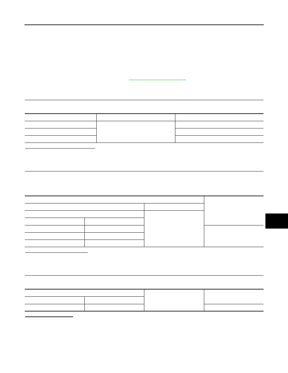
1.
CHECK FUSE AND FUSIBLE LINK
Check if the following BCM fuses or fusible link are blown.
Is the fuse or fusible link blown?
YES
>> Replace the blown fuse or fusible link after repairing the affected circuit.
NO
>> GO TO 2
2.
CHECK POWER SUPPLY CIRCUIT
1. Turn ignition switch OFF.
2. Disconnect BCM.
3. Check voltage between BCM harness connector and ground.
Is the measurement normal?
YES
>> GO TO 3
NO
>> Repair or replace harness.
3.
CHECK GROUND CIRCUIT
Check continuity between BCM harness connector and ground.
Does continuity exist?
YES
>> Inspection End.
NO
>> Repair or replace harness.
SUNROOF MOTOR ASSEMBLY
SUNROOF MOTOR ASSEMBLY : Description
INFOID:0000000009465669
• BCM supplies power.
Terminal No.
Signal name
Fuse and fusible link No.
1
Battery power supply
H
11
10
24
7
Terminals
Voltage
(Approx.)
(+)
(
−)
BCM
Ground
Connector
Terminal
M16
1
Battery voltage
M17
11
M18
24
BCM
Ground
Continuity
Connector
Terminal
M17
13
Yes