Nissan Maxima. Manual - part 544
EM-64
< REMOVAL AND INSTALLATION >
TIMING CHAIN
TIMING CHAIN
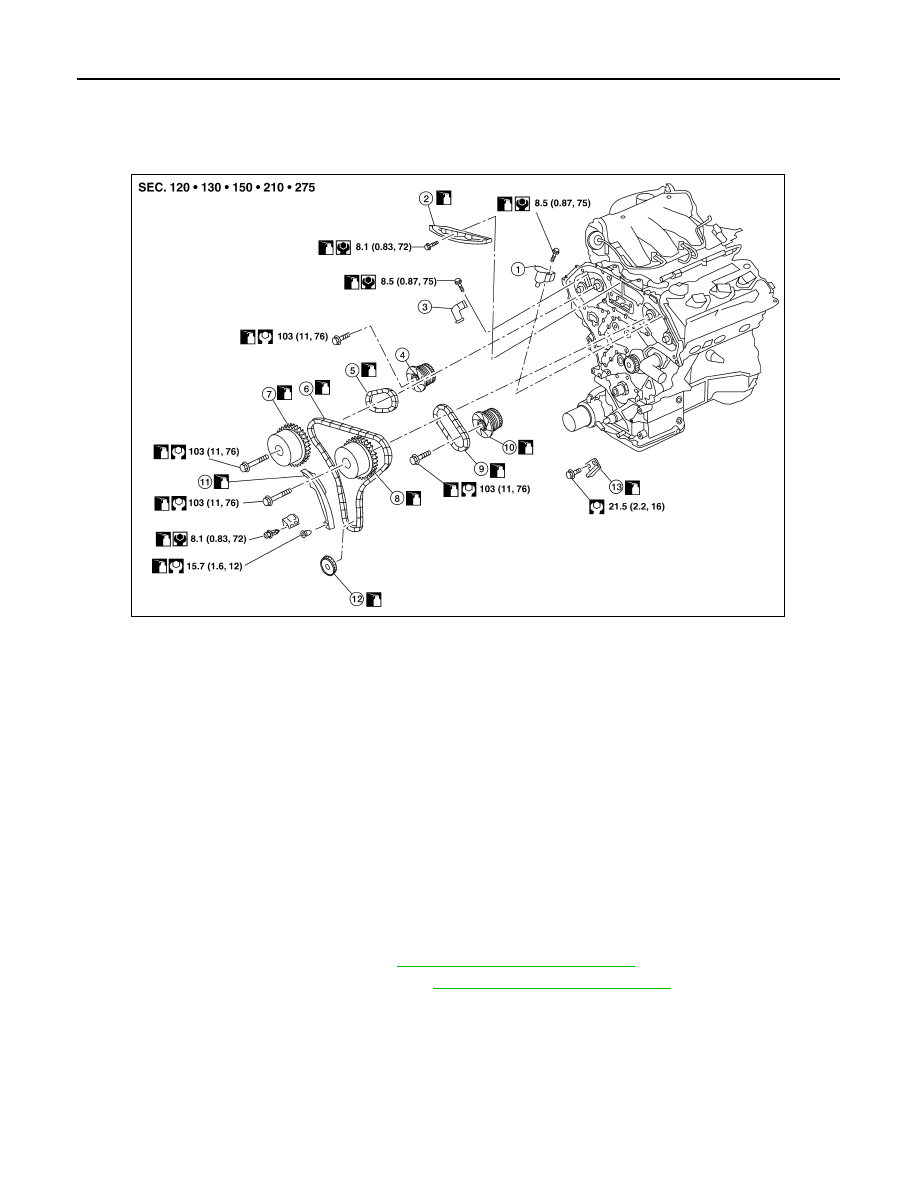
Exploded View
INFOID:0000000009466035
Removal and Installation
INFOID:0000000009466036
CAUTION:
• After removing timing chains, do not turn the crankshaft and camshaft separately, or the valves will
strike the pistons.
• When installing camshafts, chain tensioners, oil seals, or other sliding parts, lubricate contacting
surfaces with new engine oil.
• Apply new engine oil to bolt threads and seat surfaces when installing camshaft sprockets, camshaft
brackets, and crankshaft pulley.
REMOVAL
1. Remove front timing chain case. Refer to
EM-54, "Removal and Installation"
2. Remove the intake manifold collector. Refer to
EM-25, "Removal and Installation"
.
3. Remove the engine oil dipstick.
4. Place paint marks on the timing chain and sprockets to indicate the correct position of the components for
installation.
5. Remove the timing chain tensioner (primary).
1.
Timing chain tensioner (secondary) 2.
Internal chain guide
3.
Timing chain tensioner (sec-
ondary)
4.
Camshaft sprocket (EXH)
5.
Timing chain (secondary)
6.
Timing chain (primary)
7.
Camshaft sprocket (INT)
8.
Camshaft sprocket (INT)
9.
Timing chain (secondary)
10. Camshaft sprocket (EXH)
11. Slack guide
12. Crankshaft sprocket
13. Tension guide
AWBIA0838GB