Nissan Maxima. Manual - part 533


  Index      Nissan     Nissan Maxima (2009-2014 year) - Service and Repair Manual


Search            


Content   ..  531  532  533  534   ..


Nissan Maxima. Manual - part 533


EM-20

< PERIODIC MAINTENANCE >

CAMSHAFT VALVE CLEARANCE

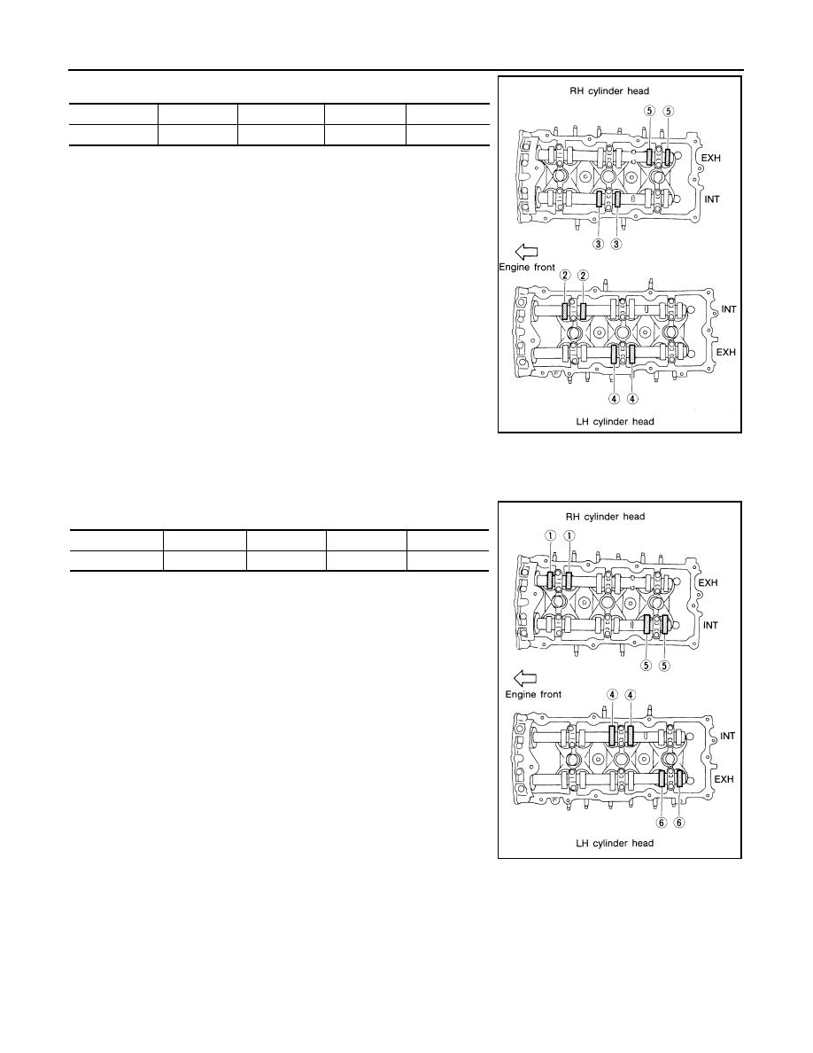
9. Check only those valve lifters as shown.

10. Turn the crankshaft 240

°.

11. Set No.5 cylinder at TDC on its compression stroke.
12. Check only those valve lifters as shown.

13. If all valve lifter clearances are within specification, install the following components. If the valve lifter

clearances are out of specification, adjust the valve lifter clearances.

• Intake manifold collectors

• Rocker covers

• All spark plugs

• All ignition coils

VALVE LIFTER ADJUSTING

Crank Position

Valve No. 2

Valve No. 3

Valve No. 4

Valve No. 5

No. 3 TDC

Intake

Intake

Exhaust

Exhaust

SEM894E

Crank Position

Valve No. 1

Valve No. 4

Valve No. 5

Valve No. 6

No. 5 TDC

Exhaust

Intake

Intake

Exhaust

SEM958E

CAMSHAFT VALVE CLEARANCE

EM-21

< PERIODIC MAINTENANCE >

C

D

E

F

G

H

I

J

K

L

M

A

EM

N

P

O

CAUTION:

Adjust valve lifter clearance while engine is cold.

NOTE:

• Perform adjustment by selecting the correct head thickness of the valve lifter (adjusting shims are not used).

• The specified valve lifter thickness is the dimension at normal temperatures. Ignore dimensional differences

caused by temperature. Use specifications for hot engine condition to confirm valve lifter clearances.

1. Remove the camshaft. Refer to 

EM-76, "Removal and Installation"

.

2. Remove the valve lifter that was measured as being outside the standard specifications.
3. Measure the center thickness of the removed valve lifter using

suitable tool as shown.

4. Use the equation below to calculate the replacement valve lifter

thickness.

Valve lifter thickness calculation equation: t = t1 + (C1 - C2)

t = thickness of the replacement valve lifter

t1 = thickness of the removed valve lifter

C1 = measured valve lifter clearance

C2 = standard valve lifter clearance

• The thickness of the new valve lifter can be identified by the

stamp mark on the reverse side (inside the valve lifter).

• Available thickness of the valve lifter (factory setting):

7.88 - 8.40 mm (0.3102 - 0.3307 in), in 0.02 mm (0.0008 in)

increments, in 27 sizes (intake/exhaust). Refer to 

EM-130,

"Camshaft"

.

5. Install the selected replacement valve lifter.
6. Install the camshaft. Refer to 

EM-76, "Removal and Installation"

.

7. Rotate the crankshaft a few turns by hand.
8. Confirm that the valve lifter clearances are within specification.
9. After the engine has been run to full operating temperature, confirm that the valve lifter clearances are

within specification.

* Approximately 80

°C (176°F)

SEM754G

SEM755G

Standard Valve Clearance

Cold

Hot* (reference data)

Intake

0.26 - 0.34 mm (0.010 - 0.013 in)

0.304 - 0.416 mm (0.012 - 0.016 in)

Exhaust

0.29 - 0.37 mm (0.011 - 0.015 in)

0.308 - 0.432 mm (0.012 - 0.017 in)

EM-22

< PERIODIC MAINTENANCE >

COMPRESSION PRESSURE

COMPRESSION PRESSURE

On-Vehicle Service

INFOID:0000000009466010

CHECKING COMPRESSION PRESSURE

1. Run the engine until it reaches normal operating temperature.
2. Turn the ignition switch to OFF.
3. Release fuel pressure. Refer to 

EC-592, "Inspection"

.

4. Remove all six spark plugs.

Refer to 

EM-12, "Removal and Installation"

.

5. Attach a compression tester to No. 1 cylinder.

6. Depress accelerator pedal fully to keep the electric throttle control actuator butterfly-valve wide open to

maximize air intake flow.

7. Crank the engine and record the highest gauge indication.
8. Repeat the measurement on each cylinder (steps 5 - 7).

Unit: kPa (kg/cm

2

, psi)/rpm

• Always use a fully-charged battery to obtain specified engine speed.

• If the engine speed is out of the specified range check the battery and recharge as necessary. Check

the engine speed again with the battery properly charged. 

• If some cylinders have low compression pressure, pour a small amount of engine oil into the spark plug

hole of the cylinder to re-check it for compression.

- If the added engine oil improves the compression, piston rings may be worn out or damaged. Check the

piston rings and replace if necessary

- If the compression pressure remains at low level despite the addition of engine oil, the valves may be

malfunctioning. Check the valves for damage. Replace the valve or valve seat accordingly.   

• If two adjacent cylinders have respectively low compression pressure and their compression remains

low even after the addition of engine oil, cylinder head gaskets may be leaking, or a valve in adjacent

cylinders may be damaged. Inspect and repair as required.

• If the compression pressure is below the minimum value, check the valve clearances and parts associ-

ated with the combustion chamber (valve, valve seat, piston, piston ring, cylinder bore, cylinder head,

cylinder head gasket). After the checking, measure the compression pressure again.

SBIA0533E

Standard

Minimum

Difference limit between cylinders

1,275 (13.0, 185)/300

981 (10.0, 142)/300

98 (1.0, 14)/300

ENGINE ROOM COVER

EM-23

< REMOVAL AND INSTALLATION >

C

D

E

F

G

H

I

J

K

L

M

A

EM

N

P

O

REMOVAL AND INSTALLATION

ENGINE ROOM COVER

Removal and Installation

INFOID:0000000009466011

CAUTION:

Do not damage or scratch engine room cover when installing or removing. 

REMOVAL

• Remove the engine room cover bolts and engine room cover.

INSTALLATION

Installation is in the reverse order of removal.

AWBIA0718ZZ


Content   ..  531  532  533  534   ..