Nissan Maxima. Manual - part 441
EC-248
< DTC/CIRCUIT DIAGNOSIS >
[VQ35DE]
P0139, P0159 HO2S2
3.
PERFORM DTC CONFIRMATION PROCEDURE
With CONSULT
1. Turn ignition switch ON and select “DATA MONITOR” mode with CONSULT.
2. Start engine and warm it up to the normal operating temperature.
3. Turn ignition switch OFF and wait at least 10 seconds.
4. Turn ignition switch ON.
5. Turn ignition switch OFF and wait at least 10 seconds.
6. Start engine and keep the engine speed between 3,500 and 4,000 rpm for at least 1 minute under no load.
7. Let engine idle for 1 minute.
8. Make sure that “COOLAN TEMP/S” indicates more than 70
°C (158°F).
9. Drive the vehicle in a proper gear at 60 km/h (38MPH) and maintain the speed.
CAUTION:
Always drive vehicle at a safe speed.
10. Release the accelerator pedal fully at least 5 seconds.
CAUTION:
• Enable the engine brake.
• Always drive carefully.
• Never apply brake when releasing the accelerator pedal.
11. Repeat step 9 and 10 at least 8 times.
12. Check the following item of “DATA MONITOR”.
Is “CMPLT” displayed on CONSULT screen?
YES
>> GO TO 6.
NO-1: “CMPLT” is not displayed on DIAG 1>>Perform DTC confirmation procedure again.
NO-2: “CMPLT” is not displayed on DIAG 2>>GO TO 4.
4.
PERFORM DTC WORK SUPPORT
1. Open engine hood.
2. Select “HO2S2 (B1) P0139” or “HO2S2 (B2) P0159” of “HO2S2” in “DTC WORK SUPPORT” mode with
CONSULT.
3. Start engine and follow the instruction of CONSULT display.
NOTE:
It will take at most 10 minutes until “COMPLETED” is displayed.
Is “COMPLETED” displayed on CONSULT screen?
YES
>> GO TO 6.
NO
>> GO TO 5.
5.
PERFORM DTC CONFIRMATION PROCEDURE AGAIN
1. Turn ignition switch OFF and leave the vehicle in a cool place (soak the vehicle).
2. Perform DTC confirmation procedure again.
>> GO TO 3.
6.
PERFORM SELF-DIAGNOSIS
With CONSULT-III
Perform ECM self-diagnosis.
Is DTC “P0139” or “P0159” detected?
YES
>> Proceed to
.
NO
>> INSPECTION END
7.
PERFORM COMPONENT FUNCTION CHECK
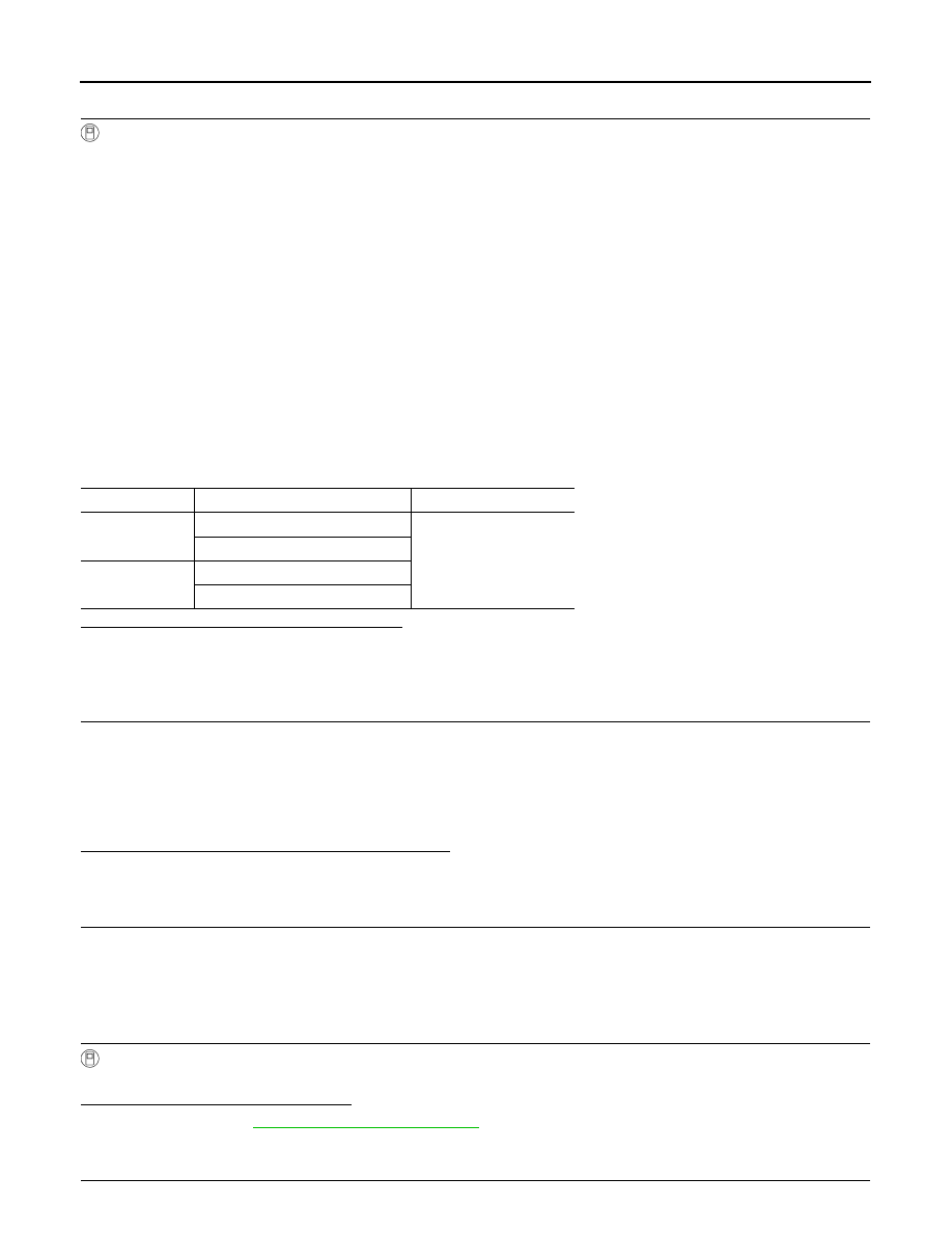
DTC
Data monitor item
Status
P0139
HO2 S2 DIAG1(B1)
CMPLT
HO2 S2 DIAG2(B1)
P0159
HO2 S2 DIAG1(B2)
HO2 S2 DIAG2(B2)