Nissan Altima HL32 Hybrid. Manual - part 349
EC-380
< COMPONENT DIAGNOSIS >
[QR25DE]
ASCD BRAKE SWITCH
• Junction block connector E46, E48
• 10A fuse (No. 3)
• Harness for open or short between ASCD brake switch and fuse
>> Repair open circuit or short to ground or short to power in harness or connectors.
3.
CHECK ASCD BRAKE SWITCH INPUT SIGNAL CIRCUIT FOR OPEN AND SHORT
1. Turn ignition switch OFF.
2. Disconnect ECM harness connector.
3. Check the continuity between ASCD brake switch harness connector and ECM harness connector.
4. Also check harness for short to ground and short to power.
Is the inspection result normal?
YES
>> GO TO 5.
NO
>> GO TO 4.
4.
DETECT MALFUNCTIONING PART
Check the following.
• Junction block connector E45, E46
• Harness for open or short between ASCD brake switch and fuse
>> Repair open circuit or short to ground or short to power in harness or connectors.
5.
CHECK ASCD BRAKE SWITCH
EC-380, "Component Inspection (ASCD Brake Switch)"
.
Is the inspection result normal?
YES
>> GO TO 6.
NO
>> Replace ASCD brake switch.
6.
CHECK INTERMITTENT INCIDENT
GI-42, "Intermittent Incident"
>> INSPECTION END
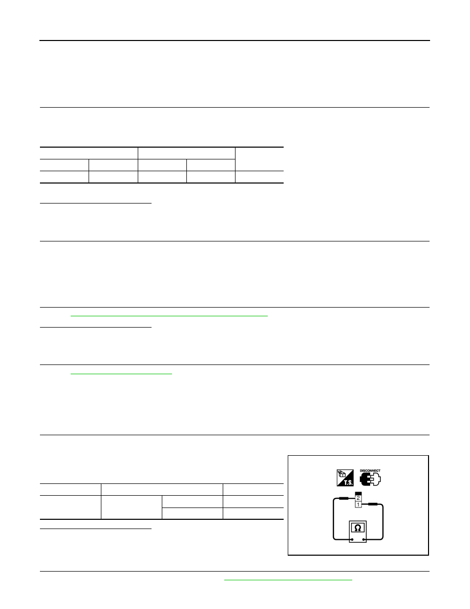
Component Inspection (ASCD Brake Switch)
INFOID:0000000004363302
1.
CHECK ASCD BRAKE SWITCH-I
1. Turn ignition switch OFF.
2. Disconnect ASCD brake switch harness connector.
3. Check the continuity between ASCD brake switch terminals
under the following conditions.
Is the inspection result normal?
YES
>> INSPECTION END
NO
>> GO TO 2.
2.
CHECK ASCD BRAKE SWITCH-II
1. Adjust ASCD brake switch installation. Refer to
BR-12, "Inspection and Adjustment"
ASCD brake switch
ECM
Continuity
Connector
Terminal
Connector
Terminal
E37
2
E10
110
Existed
Terminals
Condition
Continuity
1 and 2
Brake pedal
Fully released
Existed
Slightly depressed
Not existed
SEC023D