Nissan Altima HL32 Hybrid. Manual - part 152


  Index      Nissan     Nissan Altima HL32 Hybrid (2009 year) - Service and Repair Manual


Search            


Content   ..  150  151  152  153   ..


Nissan Altima HL32 Hybrid. Manual - part 152


ABS WARNING LAMP REMAINS ON

BRC-173

< SYMPTOM DIAGNOSIS >

[VDC/TCS/ABS]

C

D

E

G

H

I

J

K

L

M

A

B

BRC

N

O

P

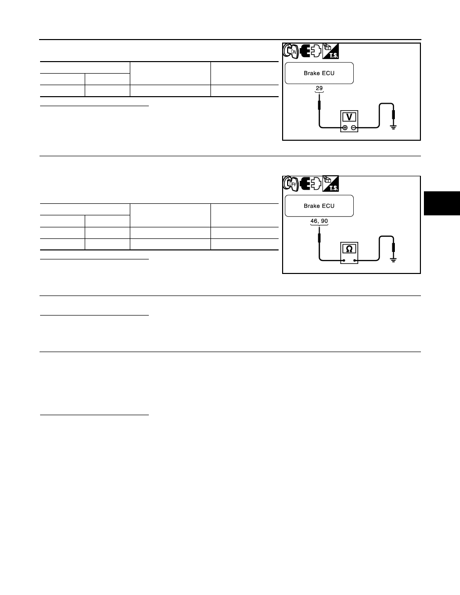
3. Measure the voltage according to the value(s) in the table below.

Is the inspection result normal?

YES

>> GO TO 5.

NO

>> Repair or replace harness or connector (IG1 circuit).

5.

INSPECT BRAKE ECU (GND TERMINAL)

1. Turn the ignition switch OFF.

2. Disconnect the brake ECU connectors.

3. Measure the resistance according to the value(s) in the table

below.

Is the inspection result normal?

YES

>> GO TO 6.

NO

>> Repair or replace harness or connector (GND circuit).

6.

INSPECT HV ECU

Perform HV ECU self-diagnosis.
Is the inspection result normal?

YES

>> Repair or replace malfunctioning components.

NO

>> GO TO 7.

7.

INSPECT COMBINATION METER ASSEMBLY

1. Reconnect the brake ECU connectors.

2. Perform “ABS WARN LAMP” of the combination meter (meter CPU) using the “ACTIVE TEST”.

NOTE:

• The ABS warning lamp turns ON or OFF in accordance with the CONSULT-III.

• If troubleshooting has been carried out according to the Problem Symptoms Table, refer back to the

table and proceed to the next step before replacing part.

Is the inspection result normal?

YES

>> Replace brake ECU.

NO

>> Replace combination meter assembly.

Brake ECU

Condition

Specified condition

Connector

Terminal

E60

29 – Ground

Ignition switch ON

10 to 14 V

JSFIA0373GB

Brake ECU

Condition

Specified condition

Connector

Terminal

E60

46 – Ground

Always

Below 1 

E61

90 – Ground

Always

Below 1 

JSFIA0374GB

BRC-174

< SYMPTOM DIAGNOSIS >

[VDC/TCS/ABS]

ABS WARNING LAMP DOES NOT COME ON

ABS WARNING LAMP DOES NOT COME ON

Description

INFOID:0000000004212744

The brake ECU is connected to the combination meter with CAN communication via HV ECU.

Diagnosis Procedure

INFOID:0000000004212745

CAUTION:

When replacing the brake ECU, perform initialization of linear solenoid valve and calibration.

1.

CHECK CAN COMMUNICATION SYSTEM

Check if the CAN communication system DTC is output.

Result

A

>> GO  TO  2.

B

>> Inspect CAN communication system.

2.

INSPECT HV ECU

Perform HV ECU self-diagnosis.
Is the inspection result normal?

YES

>> Repair or replace malfunctioning components.

NO

>> GO TO 3.

3.

CHECK ABS WARNING LAMP

1. Disconnect the brake ECU connector.

2. Turn the ignition switch ON.

3. Check that the ABS warning lamp come ON.

NOTE:

• The ABS warning lamp comes ON.

• If troubleshooting has been carried out according to the Problem Symptoms Table, refer back to the

table and proceed to the next step before replacing the part.

Is the inspection result normal?

YES

>> Replace brake ECU.

NO

>> GO TO 4.

4.

INSPECT COMBINATION METER ASSEMBLY

1. Turn the ignition switch OFF.

2. Reconnect the brake ECU connector.

3. Perform “ABS WARN LAMP” of the combination meter (meter CPU) using the “ACTIVE TEST”.

NOTE:

• The ABS warning lamp turns ON or OFF in accordance with the CONSULT-III.

• If troubleshooting has been carried out according to the Problem Symptoms Table, refer back to the

table and proceed to the next step.

Is the inspection result normal?

YES

>> Replace brake ECU.

NO

>> Replace combination meter assembly.

Condition

Proceed to

DTC is not output.

A

DTC is output.

B

VDC WARNING LAMP REMAINS ON

BRC-175

< SYMPTOM DIAGNOSIS >

[VDC/TCS/ABS]

C

D

E

G

H

I

J

K

L

M

A

B

BRC

N

O

P

VDC WARNING LAMP REMAINS ON

Description

INFOID:0000000004212746

The brake ECU communicates with the combination meter with CAN communication via HV ECU. If the ECU

stores a DTC, the VDC warning lamp will come ON.

Diagnosis Procedure

INFOID:0000000004212747

NOTE:

When removing battery, VDC warning lamp turns ON because the stored zero point of steering angle is

erased. In this case, when driving in a straight line at 35 km/h (22 MPH) for 5 seconds or more, zero adjust-

ment completes and VDC warning lamp turns OFF.

CAUTION:

When replacing the brake ECU, perform initialization of linear solenoid valve and calibration.

1.

CHECK CAN COMMUNICATION SYSTEM

Check if the CAN communication system DTC is output.

Result

A

>> GO TO 2.

B

>> Inspect CAN communication system.

2.

INSPECT HV ECU

Perform HV ECU self-diagnosis.
Is the inspection result normal?

YES

>> Repair or replace malfunctioning components.

NO

>> GO TO 3.

3.

CHECK IF BRAKE ECU CONNECTOR IS SECURELY CONNECTED

Check if the brake ECU connector is securely connected.

NOTE:

The connector should be securely connected.
Is the inspection result normal?

YES

>> GO TO 4.

NO

>> Connect connector to ECU correctly.

4.

CHECK AUXILIARY BATTERY

Check the auxiliary battery voltage.

Is the inspection result normal?

YES

>> GO TO 5.

NO

>> Charge or replace auxiliary battery.

5.

INSPECT COMBINATION METER ASSEMBLY

Perform “VDC WARN LAMP” of the combination meter (meter CPU) using the “ACTIVE TEST”.

NOTE:

• The VDC warning lamp turns ON or OFF in accordance with the CONSULT-III.

• If troubleshooting has been carried out according to the Problem Symptoms Table, refer back to the table

and proceed to the next step.

Is the inspection result normal?

YES

>> Replace brake ECU.

NO

>> Replace combination meter assembly.

Condition

Proceed to

DTC is not output.

A

DTC is output.

B

Standard voltage : 11 to 14 V

BRC-176

< SYMPTOM DIAGNOSIS >

[VDC/TCS/ABS]

VDC WARNING LAMP DOES NOT COME ON

VDC WARNING LAMP DOES NOT COME ON

Description

INFOID:0000000004212748

The brake ECU communicates with the combination meter with CAN communication via HV ECU. If the ECU

stores a DTC, the VDC warning lamp will come ON.

Diagnosis Procedure

INFOID:0000000004212749

CAUTION:

When replacing the brake ECU, perform initialization of linear solenoid valve and calibration.

1.

CHECK CAN COMMUNICATION SYSTEM

Check if the CAN communication system DTC is output.

Result

A

>> GO  TO  2.

B

>> Inspect CAN communication system.

2.

INSPECT HV ECU

Perform HV ECU self-diagnosis.
Is the inspection result normal?

YES

>> Repair or replace malfunctioning components.

NO

>> GO TO 3.

3.

CHECK VDC WARNING LAMP

1. Connect the CONSULT-III.

2. Turn the ignition switch ON (READY).

3. Select “VDC WARN LAMP” in the “ACTIVE TEST” and operate the VDC warning lamp using the CON-

SULT-III.

ABS/VDC:

4. Check that “ON” and “OFF” of the VDC warning lamp are indicated on the combination meter when using

the CONSULT-III.

NOTE:

• The VDC warning lamp turns ON or OFF in accordance with the CONSULT-III.

• If troubleshooting has been carried out according to the Problem Symptoms Table, refer back to the

table and proceed to the next step.

Is the inspection result normal?

YES

>> GO TO 4.

NO

>> Replace brake ECU.

4.

INSPECT COMBINATION METER ASSEMBLY

1. Turn the ignition switch OFF.

2. Perform “VDC WARN LAMP” of the combination meter (meter CPU) using the “ACTIVE TEST”.

NOTE:

• The VDC warning lamp turns ON or OFF in accordance with the CONSULT-III.

• If troubleshooting has been carried out according to the Problem Symptoms Table, refer back to the

table and proceed to the next step.

Is the inspection result normal?

YES

>> Replace brake ECU.

NO

>> Replace combination meter assembly.

Condition

Proceed to

DTC is not output.

A

DTC is output.

B

Tester display

Test part

Control range

Diagnostic note

VDC WARN LAMP

VDC warning lamp 

Warning lamp ON/OFF

Observe combination meter


Content   ..  150  151  152  153   ..