Content .. 998 999 1000 1001 ..
Nissan Altima HL32 Hybrid. Manual - part 1000
B2612 STEERING STATUS
SEC-73
< COMPONENT DIAGNOSIS >
[INTELLIGENT KEY SYSTEM]
C
D
E
F
G
H
I
J
L
M
A
B
SEC
N
O
P
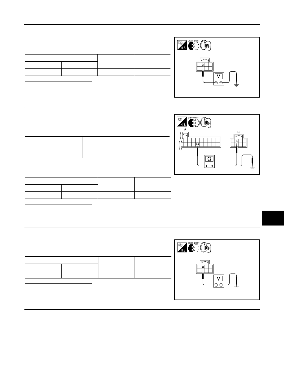
1. Turn ignition switch OFF.
2. Disconnect steering lock unit harness connector and IPDM E/R harness connector.
3. Check voltage between steering lock unit harness connector
and ground.
Is the inspection result normal?
YES
>> GO TO 4
NO
>> GO TO 3
3.
CHECK STEERING LOCK UNIT CIRCUIT-I
1. Disconnect BCM harness connector.
2. Check continuity between BCM harness connector M19 (A) ter-
minal 85 and steering lock unit harness connector M32 (B) ter-
minal 3.
3. Check continuity between BCM harness connector M19 (A) ter-
minal 85 and ground.
Is the inspection result normal?
YES
>> GO TO 6
NO
>> Repair harness or connector.
4.
CHECK IPDM E/R OUTPUT SIGNAL
1. Connect IPDM E/R harness connector.
2. Disconnect BCM harness connector.
3. Check voltage between steering lock unit harness connector
and ground.
Is the inspection result normal?
YES
>> Replace steering lock unit.
NO
>> GO TO 5
5.
CHECK STEERING LOCK UNIT CIRCUIT-II
Steering lock unit
Ground
Voltage [V]
Connector
Terminal
M32
3
Ground
Battery voltage
ALKIA0454ZZ
BCM
Steering lock unit
Continuity
Connector
Terminal
Connector
Terminal
A: M19
85
B: M32
3
Yes
BCM
Ground
Continuity
Connector
Terminal
A: M19
85
Ground
No
ALKIA0455ZZ
Steering lock unit
Ground
Voltage [V]
Connector
Terminal
M32
3
Ground
Battery voltage
ALKIA0454ZZ