Nissan PULSAR N13 Series / ASTRA LD Series. Manual - part 48


  Index      Nissan     Nissan PULSAR N13 Series / ASTRA LD Series (1.6 and 1.8 Liter) 1987 – 1991 year - Service Manual


Search            


Content   ..  46  47  48  49   ..


Nissan PULSAR N13 Series / ASTRA LD Series. Manual - part 48


Electrical System


193


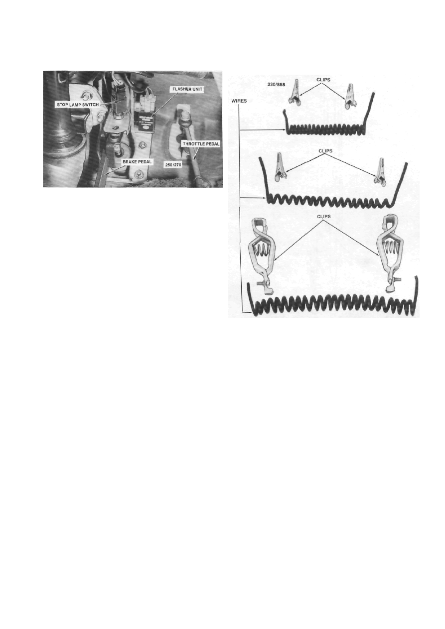
Installed view of the stop lamp switch and the flasher 

unit. 

(2) Fault in the warning lamp wiring: Check and 

repair the fault.


NOTE: When renewing bulbs ensure that a 
new bulb of the correct wattage is used.


TURN SIGNAL LAMPS FLASH WEAKLY AND 
AT GREATER THAN NORMAL SPEED


1. 

Faulty flasher unit: Check and renew the 

flasher unit. 

2. 

Front or rear bulb blown on the turn side: 

Check and renew the bulb. 

NOTE: If the flasher unit is to be renewed, 
always try to obtain a genuine replacement 
part.


HAZARD WARNING LAMPS DO NOT 
OPERATE


Fuse blown: Rectify the fault and renew as 

necessary. 


Flasher unit faulty: Renew the flasher unit. 


Hazard  warning switch  faulty:  Renew the 

switch. 


Fault in the wiring circuit: Check and repair 

the fault. 

5.    TEST EQUIPMENT AND SOME 

APPLICATIONS


Special Equipment Required:


To Make Test Lamp or Jumper Lead — Soldering 
iron


When working on the electrical system, a test 

lamp and jumper leads can be very useful to check 
circuits.


TO MAKE A JUMPER LEAD


The minimum materials required to make a 

jumper lead are one length of 4 mm wire and two 
small alligator clips.


Grouping of materials to construct jumper leads of 

various sizes. 


Bare both ends of a suitable length of 4 mm 

wire. 


Connect a small alligator clip to each end of 

the wire. Solder and tape the connections. 


Test the jumper lead for continuity by re- 

moving one battery cable and connecting the lead 
between the cable and the battery terminal. Turn the 
ignition On and the dashboard warning lamps should 
operate indicating a completed circuit through the 
jumper lead. 


Remove the jumper lead from the circuit and 

reconnect the battery. 

NOTE: Make a few jumper leads of various 
lengths using different sizes and types of 
alligator and battery clips.


TO MAKE TEST LAMP


Due to the extensive use of electronic components 

in the electrical system, an LED (light emitting diode) 
test lamp can be made from a suitable length of 3 mm 
wire, an alligator clip, an LED, a 1/4 watt 560 ohm 
resistor, a suitable case such as an old ball point pen 
case and a length of rod or wire sharpened to form a 
probe.


(1)   Solder the length of wire to the K (cathode)


194


Electrical System


Schematic of LED test lamp. Ensure that the connec- 

tions to the K (cathode) lead and A (anode) lead of the 

LED are as illustrated. 

lead of the LED. The K lead is the shorter of the two 
leads and is adjacent to the flat on the LED.


Solder the 560 ohm resister to the A (anode) 

lead of the LED. 


Solder a short length of wire to the other lead 

of the resistor and to the probe. 


Drill a hole in the side of the case to accept 

the wire attached to the K lead of the LED. 


Mount the probe in the case. If using a pen 

case, push the probe through the lower end of the pen 
after removing the refill. 


Push the lead attached to the K lead of the 

LED through the hole made in the side of the case and 
solder the alligator clip to the lead. 


Mount the LED to the case. If using a pen 

case, the LED may be mounted in the plug at the top 
of the pen after drilling the plug to accept the LED. 


Suitably attach the probe to the case using 

adhesive or tape. 

TO TEST SWITCHES


Disconnect the wires from the switch. 


Using a test lamp, test each wire to locate the 

power wire. It may be necessary to turn the ignition 
On as the switch may be wired through the ignition 
circuit. 


Disconnect  the test lamp and connect a 

jumper lead between the power wire and the wire 
from the other side of the switch.


If the circuit functions, the switch can be consid- 

ered faulty and should be renewed. Refer to the 
heading Switches and Controls.


TO TEST BULBS


Remove the bulb from the bulb holder. 


Connect a jumper lead between the positive 

terminal of a battery and the base of the bulb. 


Connect another jumper lead between the 

negative battery terminal and the contact on the base 
of the bulb. The bulb should illuminate. 

If the bulb has two filaments, connect the jumper 

lead to the second contact on the base of the bulb. The 
second filament should illuminate.


If the bulb fails to illuminate, it should be 

renewed with a bulb of the correct voltage and 
wattage.


TO TEST CIRCUITS


Turn the circuit switch On. 


Using a test lamp, check for power at one of 

the circuit connections. A fuse is a good starting point. 

If power is available, reconnect the connector and 

continue checking towards the motor or bulb end of 
the circuit.


If power is not available, continue checking 

towards the battery or switch end of the circuit.


6.    BATTERY


Special Equipment Required: 

To Test — Hydrometer 
To Charge — Battery charger


TO REMOVE AND INSTAL


(1) Disconnect the negative and positive battery 

terminals.


Installed view of the battery

Electrical System


195


(2) Remove the battery holding clamp and lift 

the battery from the vehicle.


Installation is a reversal of the removal procedure 

with attention to the following points:


Ensure  that the terminals and posts are 

clean. 


When connecting the leads to the battery, 

ensure  that  the   polarity   is  correct.   Connect   the 
positive lead first. 


Do not over tighten the terminal clamp 

nuts. 
 

Apply petroleum jelly to the battery termi- 

nals to prevent corrosion. 

MAINTENANCE


Battery maintenance should be performed at the 

scheduled services.


NOTE: Keep naked flames away from the 
battery as the battery gases are highly 
explosive.


(1)  Keep the battery and the surrounding area 

clean and dry. In particular, ensure that the top of the 
battery is free from dirt and moisture to prevent a 
voltage drop between the terminals.


If necessary, clean the battery case as follows:


Remove the  battery  from  the  vehicle as 

previously described. 


Pour hot water over the battery being careful 

not to allow any water to enter the battery through the 
filler cap vent holes. 


Wipe the battery case clean. 


Clean the battery terminals and posts using a 

battery   post  cleaner,   wire  brush   or  emery  cloth. 
Remove all dirt and corrosion. 


Remove the filler caps and check that the 

vent holes are clear. 


Check the electrolyte level and replenish with 

distilled water as necessary. The correct level is just 
above the top of the plates. Do not overfill the battery. 
Do not transfer electrolyte from one cell to another.


(5)  If the battery electrolyte requires frequent 

replenishing, check the battery case for cracks. If the 
case is damaged, renew the battery.


Check for overcharging by measuring the output 

of the alternator as described later in this section.


Apply petroleum jelly to the battery termi- 

nals to prevent corrosion. 


If the electrolyte has overflowed and contam- 

inated   the  battery  carrier  and  surrounding body 
panels, proceed as follows: 


With the battery removed from the vehicle, 

sprinkle bicarbonate of soda over the contaminated 
areas. 


Pour hot water over the bicarbonate of soda. 

The bicarbonate of soda will react with the water and 
begin to foam. 


When the bicarbonate of soda has stopped 

foaming, rinse the area with clean water and allow to 
dry. 


Remove any blistered paint from the con- 

laminated areas. 


Paint the contaminated areas with a corro- 

sion inhibiting paint. 

TO TEST AND CHARGE


(1)  Using a hydrometer, test the specific gravity 

of the battery electrolyte. Refer to the following chart 
which shows charge conditions for various specific 
gravity readings.


1.110-1.130............................... Fully discharged


1.140-1.160..............................Nearly discharged


1.170-1.190...........................Approximately one


quarter charged


1.200-1.220..................................... Half charged


1.230-1.250......................... Approximately three


quarters charged 

1.250-1.280..................................... Fully charged


These readings are for electrolyte at a temperature 

of 20 deg C. For every 10 deg above 20 deg C, add 
0.007. For every 10 deg below 20 deg C, subtract 
0.007.


NOTE: An accurate specific gravity reading 
cannot be obtained if distilled water has 
recently been added to the electrolyte. If the 
electrolyte level is below the battery plates, 
replenish with distilled water and charge the 
battery before testing the specific gravity.


(2)  If a low state of charge is indicated, or if the 

specific gravity readings vary more than 0.030 be- 
tween cells, the battery should be 'charged, using a 
battery charger, with attention to the following points:


(a) Disconnect the negative and positive battery 

terminals.


Cleaning the battery terminals using a battery post

cleaner. 

196


Electrical System 


Check the specific gravity in each cell with a hydro- 

meter. 


Check the battery electrolyte level and re- 

plenish as necessary. 


Remove the filler caps from the battery. 


Follow the battery charger manufacturers 

instructions. 

(3) Should the battery fail to operate satisfacto- 

rily after charging, it is recommended that it be taken 
to a workshop with the necessary equipment to per- 
form a load test. Load testing, when performed in 
conjunction with the specific gravity tests described 
above will give an accurate indication of the service- 
ability of the battery. 

7. ALTERNATOR 

Special Equipment Required 

To Test On Vehicle - Voltmeter, 100-0-100 
amp ammeter, ohmmeter 
To Dismantle — 200 watt soldering iron, 
bearing
 

puller, press 

To Assemble — 200 watt soldering iron 

DESCRIPTION 

Two types of alternator are installed to the range 

of vehicles covered by this manual, either Hitachi or 
Bosch. 

In the alternator, the field and pole shoe assembly 

is the moving part and it is shaped to form the rotor. 
Since only a low amperage current flows between the 
slip rings on the rotor shaft and the brushes, wear on 
the brushes and slip rings is very slight and mainte- 
nance is reduced to a minimum. 

The output current is generated in the fixed stator 

windings and is a three phase alternating current 
(AC). The stator windings are wound on a laminated 
soft iron former, star connected and installed between 
the end brackets. 

As it is not possible to charge a storage battery 

with alternating current, it is necessary to rectify the 
output of the stator windings to direct current (DC). 

This is done by a bank of diodes mounted within the 
alternator slip ring end bracket. 

The output of the alternator is governed by the 

regulator and the built in characteristics of the alter- 
nator. 

The regulator and brush holder assembly on 

Hitachi alternators is mounted within the alternator 
on the slip ring end bracket side. On Bosch 
alternators 
the regulator and brush holder unit is mounted to the 
outside of the slip ring end bracket. 

An electrical cut out unit is not necessary with the 

alternator charging system as the diodes prevent a 
reverse current flow through the alternator. 

SERVICE PRECAUTIONS 


Ensure that the battery is connected with the 

correct polarity to earth. Refer to Specifications. 


Do not short out or ground any terminals 

common to the charging circuit. 


Always disconnect the battery before con- 

necting a battery charger. 


If a booster battery is used, always connect it 

in a parallel circuit i.e. positive to positive ( + to + ) 
and negative to negative (- to -) to maintain 12 
volt supply. 


Never disconnect the battery or terminals in 

the charging circuit while the engine is running. 


Regularly check that the alternator drive belt 

tension is as specified. Refer to the Engine Tune-up 
section. 


Keep  the  battery  terminals  clean  and  all 

electrical connections tight. 


Disconnect the battery and alternator when 

electric welding on the vehicle. 

TO TEST ON VEHICLE 

If the charge indicator lamp stays on after the 

engine has been started and run at approximately 
1 000 rpm, carry out the following tests. 


Stop the engine. 


Check the condition and adjustment of the 

alternator drive belt. 


Clean the battery terminals, tighten all elec- 

trical connections, check the wiring for shorts to earth 
and/or bridged circuits. Ensure that the battery is fully 
charged.  If the battery is discharged charge it or 
replace it with one fully charged. 


Start the engine and allow it to run until 

normal operating temperature is reached. 


Stop the engine and disconnect the negative 

battery terminal. 


Remove the nut and washer from the alter- 

nator output terminal (B +) and disconnect the alter- 
nator output lead. 


Connect one lead of an ammeter to the 

alternator output terminal and the other lead to the 
lead removed from the output terminal. 


Connect the negative battery terminal and 

connect a voltmeter across the battery terminals. 


Content   ..  46  47  48  49   ..