Nissan PULSAR N13 Series / ASTRA LD Series. Manual - part 39


  Index      Nissan     Nissan PULSAR N13 Series / ASTRA LD Series (1.6 and 1.8 Liter) 1987 – 1991 year - Service Manual


Search            


Content   ..  37  38  39  40   ..


Nissan PULSAR N13 Series / ASTRA LD Series. Manual - part 39


Front Suspension


157


Check the stabilizer bar links for wear and damage. 

(3)  Incorrect front end alignment: Check and 

adjust the alignment as necessary. 

(4)  Defective stabilizer bar mounting rubbers or 

worn link ball joints: Renew component as necessary. 

(5)  Weak or broken front coil spring:  Renew 

both springs as a matching pair. 

(6)  Broken or weak rear coil spring: Renew both 

springs as matching pair. 

(7)  Drive shaft bent or distorted: Check and 

renew as necessary. 

(8)  Tie rod end worn or damaged: Check and 

renew as necessary. 

(9)  Control arm ball joint worn or damaged: 

Check and renew as necessary. 

(10)  Control arm mounting bolts loose: Tighten 

the control arm bolts. 

(11)  Wheel hub bearing worn: Check and renew 

as necessary. 

NOTE: As a quick guide to suspension unit 
condition, bounce the front of the vehicle up 
and down (one side at a time), the vehicle 
should come to rest in a single movement. If 
it bounces two or three times before stop- 
ping, the suspension unit should be renewed. 
If the from of the vehicle is tower on one 
side than the other, remove the coil spring 
and check its free length against a new 
spring. If the spring is found to be unservice- 
able it is good practice to install two new 
springs as a matching pair. This also applies 
to the springs on the rear of the vehicle.


2.    DESCRIPTION


The front suspension is an independent type 

comprising two Macpherson strut suspension units 
mounted vertically on each side of the vehicle. The 
lower end of the suspension unit is bolted to the 
steering knuckle, which in turn houses the front hub 
bearings. The steering knuckle pivots on the control 
arm by means of a ball joint.


The control arm pivots at its inner ends on rubber 

bushes.


A stabilizer bar is attached to both ends of the 

control arms using ball joint links. The stabilizer bar 
is attached to the front underbody by brackets and 
mounting rubbers.


Each front suspension unit assembly comprises a 

tubular shock absorber type suspension unit, sur- 
rounded at the upper end by a coil spring. On top of 
the coil spring is the upper mounting which attaches 
to the underside of the inner mudguard panel. The 
piston rod of the suspension unit is attached to the 
centre of the upper mounting by a rubber mounted 
bearing.


When a suspension unit is found to be defective it 

is recommended that both suspension units be re- 
newed as a pair.


Camber is adjusted by means of a cam on the 

upper steering knuckle to suspension unit mounting 
bolt.


The kingpin inclination and caster are set in 

production and cannot be adjusted. Any variation in 
these angles will be caused by worn or damaged 
components.


3.    STEERING KNUCKLE 

Special Equipment Required: 

To Renew Wheel Bearing — Press and press plates 
and suitable tubes and mandrels 
To Check Hub End Float — Dial gauge 

TO REMOVE AND INSTAL 

( 1 )  Raise the front of the vehicle and support it 

on chassis stands. Remove the front wheel.


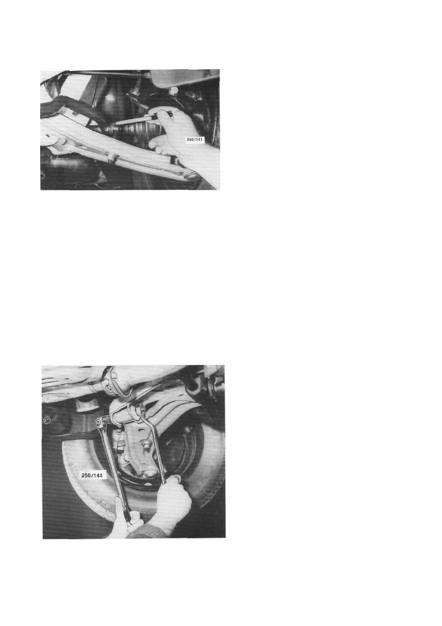
Checking the control arm bolts for security.

158 

Front Suspension


Installed view of the front suspension. When using a floor jack locate the head of the jack on the crossmember. 

(2)  Remove the cap, split  pin, castellated  re- 

tainer and with the aid of an assistant applying the 
brakes, loosen and remove the hub nut. 

(3)  Remove the split pin and the castellated nut 

retaining the tie rod end to the steering knuckle. 

(4)  Disconnect the tie rod end from the steering 

knuckle using a suitable puller. Alternatively place a 
suitable dolly or hammer against one side of the 
steering knuckle eye and strike the opposite side with 
a hammer. 

(5)  Remove the brake caliper anchor plate bolts, 

withdraw the caliper from the disc and support it with 
a piece of wire inside the inner mudguard. Ensure that 
the brake hose is not twisted. 

(6)  Withdraw the brake disc from the hub. 
(7)  Loosely install the hub nut and tap on the nut 

with a soft faced hammer to separate the drive shaft 
from the hub. 

(8)  Place a  mark on the suspension  unit to 

steering knuckle cam head bolt to ensure correct wheel 
alignment on assembly. 

(9)  Remove the steering knuckle to suspension 

unit nuts and bolts. 

(10)  Remove the split pin and the castellated nut 

retaining the lower ball joint stud to the steering 
knuckle. 

(11)  Disconnect  the  ball joint  stud  from  the 

steering knuckle using a suitable puller or alternatively 
place a suitable dolly or hammer against one side of 
the steering knuckle eye and strike the opposite side 
with a hammer.


(12)  Withdraw the  steering knuckle  from  the 

vehicle taking care not to drop the drive shaft or 
damage its boot. 

(13)  Clean and check the steering knuckle for 

wear, cracks and damage. 

(14)  If necessary, dismantle the hub and check 

the bearing assembly using the dismantling procedure 
described later in this section. 

Installation is a reversal of the removal procedure 

with attention to the following points:


(1)  Install the steering knuckle and hub assembly 

over the drive shaft and loosely install the ball joint 
stud nut and the suspension unit to knuckle bolts and 
nuts. 

(2)  Ensure that the suspension unit to steering 

knuckle cam head bolt marks are aligned and tighten 
the retaining nuts to the specified torque. 

NOTE: If the cam head bolt is not installed 
in its original position, a wheel alignment 
should be performed.


(3)  Tighten the ball joint to steering knuckle stud 

bolt to the specified torque.


Front Suspension


159


(4)  Install the tie rod end to the steering knuckle 

and tighten the castellated nut securely. Install a 
new 
split pin. 

(5)  Install the brake disc to the hub. 
(6)  Install   the   brake   caliper   to   the   steering 

knuckle and tighten the retaining bolts to the specified 
torque. 

(7)  Install the hub nut and washer to the 

drive 
shaft and with the aid of an assistant applying the 
brakes, tighten the hub nut to the specified torque. 

(8)  Install the hub nut retainer and a new 

split 
pin to the drive shaft. 

(9)  Check the hub end float as described later in 

this section. 

(10)  Install the front wheel and lower the vehicle 

to the ground. 

TO DISMANTLE


NOTE: The front wheel bearing assembly is 
non-serviceable. If the wheel bearing is dis- 
mantled for any reason it should be re- 
newed.


(1)  Remove the steering knuckle from the vehi- 

cle as previously described. 

(2)  Hold the steering knuckle assembly in a vice 

with soft jaw guards. 

(3)  Using a hammer and a suitable pipe or tube 

that pushes on the inside of the hub, drive out the 
wheel hub and outside inner race from the steering 
knuckle assembly. 

(4)  Using snap ring pliers, remove the snap ring 

that retains the outer bearing race from the wheel side 
of the steering knuckle. 

(5)  Using  a   suitable   press   and   press   plates, 

support the steering knuckle with the outside face 
downwards. To aid in dismantling, position the inside 
inner race in the bearing and press the assembly from 
the steering knuckle. Discard the bearing assembly. 

(6)  Using a bearing puller and a press, remove 

the inner race from the hub assembly. 

If the inner race cannot be removed from the hub 

in this manner, it may be necessary to grind the race


using an angle grinder and split the race using a cold 
chisel.


(7)  Thoroughly   clean   and   dry   the   steering 

knuckle and hub in a suitable solvent. 

(8)  Inspect all the components for wear, damage 

and cracks and renew if necessary. 

TO ASSEMBLE


Assembly is a reversal of the dismantling proce- 

dure with attention to the following points:


(1)  Apply grease to the oil seal lips of the new 

bearing assembly.


NOTE: Ensure that (he inside of the outer 
race of the bearing is precoated with wheel 
bearing grease. If necessary, pack the outer 
race of the wheel bearing with wheel bearing 
grease after it is installed to the steering 
knuckle.


(2)  Using the press and press plates, support the 

steering knuckle with the outside face uppermost. 
Using a suitable diameter steel tube that contacts on 
the outer race only, press the outer race full into the 
steering knuckle. 

(3)  Install the snap ring to the groove in the 

steering knuckle. 

(4)  Install the inner races to the steering 

knuckle 
and support the inner race on the press using a 
suitable tube or mandrel. 

(5)  Using the press and a suitable tube press the 

hub assembly into the steering knuckle. When using 
the press ensure that the pressing force does not 
exceed 29 kN. 

(6)  With the press exerting a force of 44.1 kN 

rotate the steering knuckle from side to side several 
turns to ensure that the wheel bearings are operating 
smoothly. 

(7)  Install the steering knuckle to the vehicle 

as 
previously described. 

TO CHECK HUB END FLOAT


(1)  Raise the front of the vehicle and support it 

on chassis stands. Remove the front wheel. 

(2)  Mount the dial gauge on the steering knuckle 

so that the dial gauge plunger is against the wheel hub. 

(3)  Zero the dial gauge and attempt to move the 

hub in and out. Total hub end float should not exceed 
0.05 mm. 

(4)  Renew the wheel bearing as previously de- 

scribed if necessary. 

4.    SUSPENSION UNIT


Special Equipment Required:


To Dismantle — Spring compressor


TO REMOVE AND DISMANTLE


(1)   Raise the front of the vehicle and support it 

on chassis stands. Remove the front wheels.


Dismantled view  of the  steering  knuckle  and  hub 

components. 

160 

Front Suspension


(2)  Disconnect the flexible brake hoses from the 

suspension unit bracket. 

(3)  Using   quick   drying   paint,   place   mating 

marks on the camber adjusting cam head bolt and the 
suspension unit lower mounting as an aid to installa- 
tion. 

(4)  Remove the bolts and  nuts  retaining the 

suspension   unit   lower   mounting   to   the   steering 
knuckle. 

(5) 

Open the bonnet and remove the nuts 

retaining the suspension unit upper mounting to the 
inner mudguard panel and remove the suspension 
unit  assembly   from   the  vehicle.   Use  care when 
removing not to damage the drive shaft boot.


(6)  Remove the dust cover and loosen the piston 

rod nut but do not remove it at this stage. 

(7)  Install a spring compressor to the 

suspension 
unit assembly. Compress the coil spring and remove 
the piston rod nut. 

(8)  Remove the washer, upper mounting assem- 

bly, the thrust washer, spring seat, insulator, coil 
spring, bump rubber and dust cover from the suspen- 
sion unit. 

(9)  Check the operation of the suspension unit. 

With the suspension unit in a vertical position, move 
the piston rod up and down a number of times. A 


Dismantled view of the front suspension unit. 

uniform resistance should be felt with no abnormal 
slack spots or noise evident. If the suspension unit is 
defective, it should be renewed.


NOTE: It is recommended that the suspen- 
sion unit on the opposite side be renewed at 
the same time.


(10)  Check the upper mounting assembly for 

damage and fatigue. Check the thrust washer for wear. 
Check all rubber components, the spring seat and 
insulator for wear, damage and deterioration. Renew 
worn or damaged components. 

(11)  Check the coil spring for fatigue by compar- 

ison with a new spring. Also check the spring for 
cracks and damage. If the coil spring is defective, it is 
recommended  that  the  springs on  both  sides be 
renewed. 

TO ASSEMBLE AND INSTAL


Assembly and installation is a reversal of the 

removal and dismantling procedure with attention to 
the following points:


View of the front suspension  unit with the spring

compressor installed. 


Content   ..  37  38  39  40   ..