Nissan PULSAR N13 Series / ASTRA LD Series. Manual - part 34


  Index      Nissan     Nissan PULSAR N13 Series / ASTRA LD Series (1.6 and 1.8 Liter) 1987 – 1991 year - Service Manual


Search            


Content   ..  32  33  34  35   ..


Nissan PULSAR N13 Series / ASTRA LD Series. Manual - part 34


Manual Transaxle and Drive Shafts


137


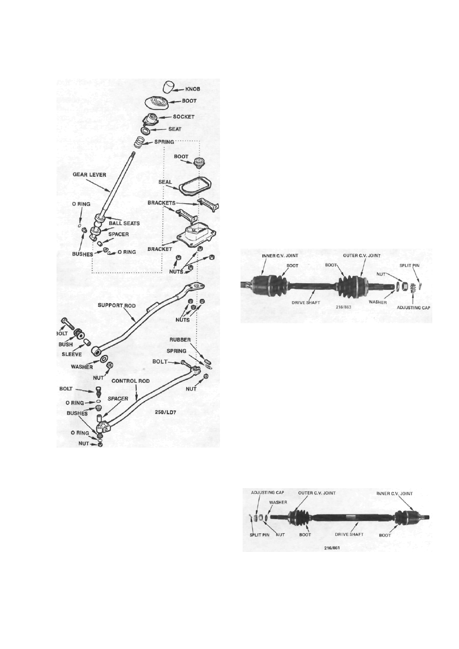
Dismantled view of the gear lever assembly.


(7)  Remove the bushes, spacer and O rings from 

the bottom of the gear lever. 

(8)  Remove the nuts retaining the floor bracket 

to the vehicle floor panel and remove the bracket from 
the vehicle. 

(9)  If necessary, disconnect the control rod and 

the support rod from the transaxle and remove the 
rods from the vehicle. 

(10)  Check all the components for deterioration, 

wear and damage. Renew the unserviceable compo- 
nents as necessary. 

Assembly is a reversal of the dismantling proce- 

dure with attention to the following points:


(1)  Install all the components to the locations 

noted during dismantling. 

(2)  Lubricate all the pivot points with multipur- 

pose grease prior to assembly. 

(3)  Tighten all the nuts securely. 
(4)  Road test the vehicle and check for correct 

gear selection. 

6.    DRIVE SHAFTS


TO REMOVE AND INSTAL


(1)  Remove the dust cap from the centre of the 

front hub. Remove the split pin and nut retainer from 
the outer end of the drive shaft. 

(2)  With an assistant applying the brakes, loosen 

the nut on the outer end of the drive shaft. 

(3)  Raise the front of the vehicle and support it 

on chassis stands. If necessary, refer to the Wheels and 
Tires section for the correct jacking points. 


Assembled view of the left hand side drive shaft 

assembly. 

(4)  Remove the split pin and castellated nut 

retaining the tie rod to the steering knuckle. 

(5)  Disconnect the tie rod end from the steering 

knuckle using a suitable puller or alternatively place a 
hammer or dolly on one side of the steering knuckle 
and strike the opposite side with a hammer. 

(6)  Remove the split pin and castellated nut 

retaining the suspension ball joint to the bottom of the 
steering knuckle. 

(7)  Disconnect the suspension ball joint from 

the steering knuckle using a suitable puller or alterna- 
tively place a hammer or dolly on one side of the 
steering knuckle and strike the opposite side with a 
hammer. 

(8)  Remove the retaining bolts and remove the 

brake caliper from the steering knuckle. Refer to the 

Assembled view of the right hand side drive shaft

assembly. 

138


Manual Transaxle and Drive Shafts


Brakes section if necessary. Suspend the caliper with 
wire or cord attached to the coil spring.


(9)  Hold the steering knuckle and hub assembly 

and tap the drive shaft out of the hub using a soft


faced hammer.


(10)  Drain  the oil from the  transaxle into a 

container. 

(11)  Prise the drive shaft out of the transaxle and 

remove the drive shaft from the vehicle. 

Installation is a reversal of the removal procedure 

with attention to the following points:


(1)  Ensure that the drive shaft is firmly attached 

to the differential side gear by attempting to pull the 
shaft out of the gear. 

(2)  Tighten all nuts securely and install new split 

pins. 

(3)  Fill the transaxle with the specified grade and 

quantity of oil. 

TO DISMANTLE AND ASSEMBLE


(1)  Remove the drive shaft from the vehicle as 

previously described. 

(2)  Remove and discard both the inner C.V. 

joint boot retaining clips from the inner C.V. joint. 

(3)  Roll back the large end of the inner C.V.- 

joint boot using a thin blade screwdriver, prise out the 
C.V. joint retaining ring. 

(4)  Withdraw the C.V. joint housing from the 

drive shaft and ball assembly. 

(5)  Remove the inner snap ring retaining the ball 

assembly to the drive shaft and withdraw the ball 
assembly. 

(6)  Remove the remaining inner C.V. joint re- 

taining snap ring and the C.V. joint boot from the 
drive shaft. 

(7)  Noting their installed positions remove the 

cage and ball assembly off the inner race and press the 
balls out of the cage. 

(8)  Remove and discard the clips retaining the 

outer C.V. joint boot to the drive shaft and remove 
the C.V. joint boot. 

NOTE:  The outer C.V. joint cannot be 
dismantled.


(9)  Wash all parts in a suitable solvent and blow 

dry with compressed air. 

(10)  Inspect the ball contact faces of the inner ball 

race and C.V. joint housing for pitting and wear. 


(11)  Inspect the ball cage and the balls for wear 

and damage. 

(12)  Rotate the drive shaft with the outer C.V. 

joint   at  a   sharp  angle  and   inspect   the   internal 
components of the outer C.V. joint for wear and 
damage. Renew if necessary by tapping the C.V. joint 
from the drive shaft. 

NOTE: Do not reuse the retaining snap ring 
if the C. V. joint is removed from the drive 
shaft.


(13)  Check the C.V. joint boots for damage and 

deterioration. 

(14)  Renew all worn or damaged components as 

necessary. 

Assembly is a reversal of the dismantling proce- 

dure with attention to the following points:


(1)  Thoroughly pack the outer C.V. joint with 

molybdenum disulphide grease. 

(2)  Install the outer C.V. joint boot and retain in 

position using new retaining clips. Ensure that the 
boot and the clips are correctly seated. 

(3)  Install the inner C.V. joint boot, small 

end 
first, onto the drive shaft and pull it well down the 
shaft. 

(4)  Install the outer snap ring for the inner C.V. 

joint into its locating groove in the drive shaft. 

(5)  Position the inner ball race inside the ball 

cage with the chamfered end of the ball race towards 
the small end of the cage. 

(6)  Press the balls firmly into the ball cage, 

ensure that the balls are fully seated. 

(7)  Install the ball assembly onto the drive 

shaft 
with the small end of the cage towards the outer C.V. 
joint and install the inner snap ring retaining the 
ball 
assembly onto the drive shaft. 

(8)  Pack  the  C.V. joint with  the  prescribed 

amount of molybdenum disulphide grease. Refer to 
Specifications. 

(9)  Install the C.V. joint retaining ring into the 

C.V. joint housing. Ensure that the retaining ring is 
correctly seated. 


Dismantled view of the inner C.V. joint. 

Install the ball assembly onto the drive shaft, with the 

small end of the cage towards the outer C.V. joint. 

Manual Transaxle and Drive Shafts


139


SNAP RING


Assembled view of the inner C.V. joint. 

(10)  Slide the large end of the inner C.V. joint 

boot over the inner C.V. joint housing and locate the 
boot in the groove in the housing. 

(11)  Pull the C.V. joint until the boot is the 

normal length. Deformation of the boot could occur if 
this operation is neglected. 

(12)  With no vacuum or pressure present in the 

C.V. joint   boot,   install   the  two  C.V. joint   boot 
retaining clips. 


Install the C.V. joint retaining ring into the C.V. joint 
housing.  Ensure that the retaining ring is correctly 

seated. 

NOTE: Ensure that the retaining dips are 
securely installed preventing the entry of 
damaging dust or water and that the lock 
tabs on the retaining clips are correctly bent 
over.


(13) Install the remaining snap ring onto the inner 

C.V. joint housing shaft and install the drive shaft to 
the vehicle as previously described.


140


AUTOMATIC TRANSAXLE


SPECIFICATIONS 

Make ..............................................JATCO RL3F01A


Type .....................3 speed and reverse epicyclic gear


train with lock up torque converter


Operation ....................................Automatic hydraulic


Lubricant:


Type....................................................... Dexron IT


Capacity.................................................  6.3 liters


TORQUE WRENCH SETTINGS


Drive plate to crankshaft bolls ........................60 Nm


Drive plate to torque converter bolts ..............49 Nm


Convener housing to engine ...........................22 Nm


Converter housing to transaxle ........................23 Nm


Transaxle sump to transaxle ............................. 7 Nm


Oil cooler pipe to transaxle .............................49 Nm


Selector shaft locknut.......................................42 Nm


Transaxle filter bolts.........................................12 Nm


1.     AUTOMATIC TRANSAXLE TROUBLE 

SHOOTING 

NO DRIVE IN D RANGE 

{1)   Low fluid level in transaxle: Check the fluid 

level in the transaxle and top up if required.


(2)  Incorrectly adjusted selector cable:  Check 

and adjust the selector cable as detailed. 

(3)  Incorrect or contaminated transaxle fluid: 

Drain and refill with the recommend type and quan- 
tity of transaxle fluid. 

NOTE: Check the possible causes in the 
order given.


NO REVERSE IN R RANGE


(1)  Low fluid level in transaxle: Check the fluid 

level and top up if required. 

(2)  Incorrectly adjusted selector linkage: Check 

the condition of the selector cable, selector quadrant 
and selector arm for wear and damage.  Adjust as 
required. 


Check the drive shaft oil seals as a likely leak source. 

SLIPPING OR ROUGH UPSHIFT


(1)  Incorrectly adjusted selector linkage: Check 

and adjust the selector linkage. 

(2)  Low fluid level in transaxle: Check the fluid 

level and top up if required. 

NO TRANSAXLE KICKDOWN 

( 1 )   Incorrectly adjusted throttle cable: Check 

and adjust the cable as detailed in the Fuel and Engine 
Management section.


Check the oil cooler hose connections for leaks if the

fluid level is low. 


Content   ..  32  33  34  35   ..