Nissan March K13. Manual - part 283
EM-66
< REMOVAL AND INSTALLATION >
[HR12DE]
CAMSHAFT
1.
Install camshaft in cylinder head. Refer to
EM-53, "Removal and Installation"
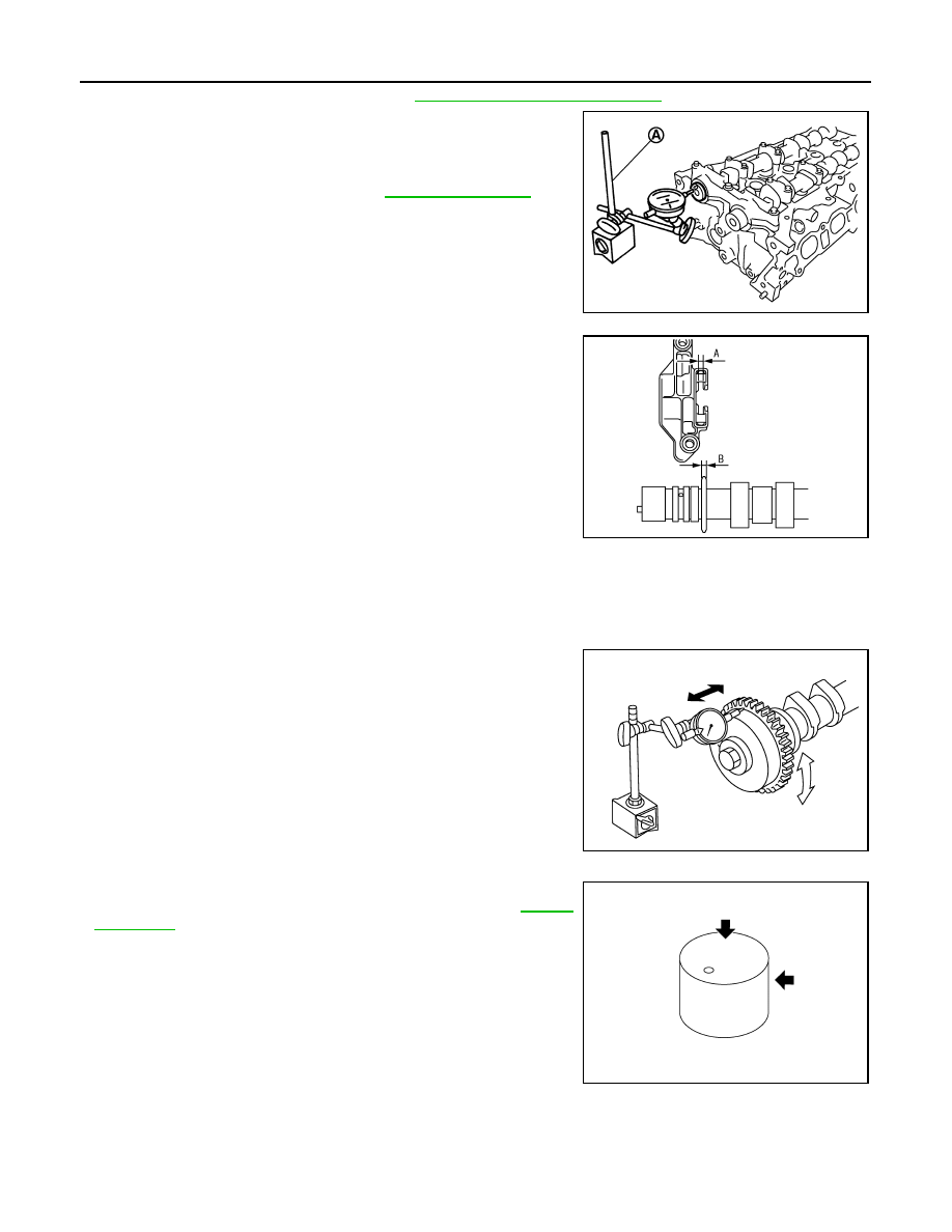
2.
Install a dial indicator (A) in thrust direction on front end of cam-
shaft. Measure the camshaft end play on the dial indicator when
camshaft is moved forward/backward (in direction to axis).
• Measure the following parts if out of the standard.
- Dimension “A” for cylinder head No. 1 journal bearing
- Dimension “B” for camshaft thrust
• Refer to the standards above, and then replace camshaft and/
or cylinder head.
Camshaft Sprocket Runout
1.
Put V-block on precise flat table, and support No. 2 and 5 journals of camshaft.
CAUTION:
Never support No. 1 journal (on the side of camshaft sprocket) because it has a different diameter
from the other four locations.
2.
Measure the camshaft sprocket runout with a dial indicator.
(Total indicator reading)
• If it exceeds the limit, replace camshaft sprocket.
Valve Lifter
Check if surface of valve lifter has any wear or cracks.
• If anything above is found, replace valve lifter. Refer to
.
Valve Lifter Clearance
VALVE LIFTER OUTER DIAMETER
Standard and Limit
: Refer to
PBIC3694E
Standard
: 4.000 - 4.030 mm (0.1574 - 0.1586 in)
Standard
: 3.877 - 3.925 mm (0.1526 - 0.1545 in)
KBIA3345J
Limit
: 0.15 mm (0.0059 in)
KBIA1493J
KBIA0182E