Nissan Silvia. Manual - part 344


  Index      Nissan     Nissan Silvia - Service Manual (2001 year)


Search            


Content   ..  342  343  344  345   ..


Nissan Silvia. Manual - part 344


SMA525A

On-vehicle Service

FRONT SUSPENSION PARTS

NMSU0006

Check front axle and front suspension parts for excessive play,
cracks, wear or other damage.

I

Shake each front wheel to check for excessive play.

I

Make sure that cotter pin is inserted.

I

Retighten all axle and suspension nuts and bolts to the speci-
fied torque.

Tightening torque:

Refer to “FRONT SUSPENSION”, SU-5.

SFA392B

I

Check strut (shock absorber) for oil leakage or other damage.

I

Check suspension ball joint for grease leakage and ball joint
dust cover for cracks or other damage.
If ball joint dust cover is cracked or damaged, replace trans-
verse link.

SFA556A

I

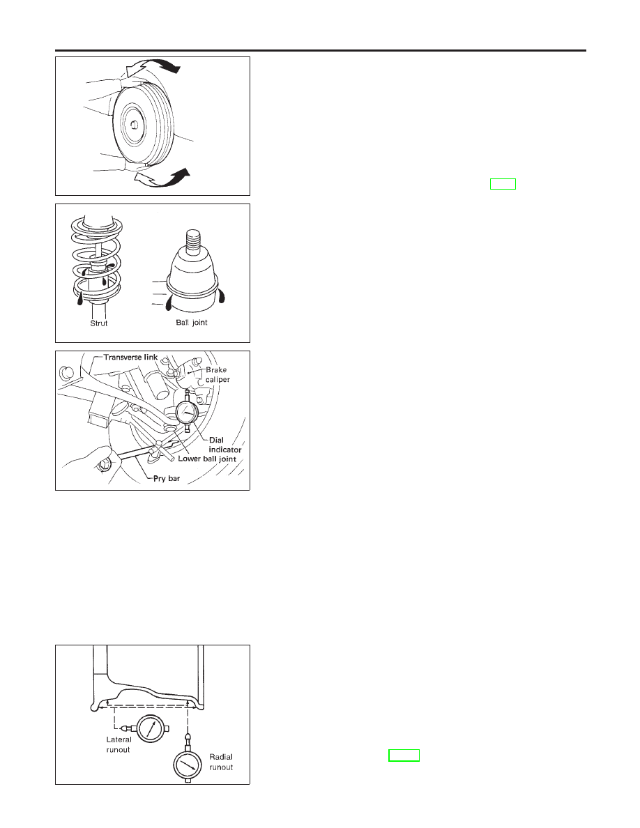
Check suspension ball joint end play.

a)

Jack up front of vehicle and set the stands.

b)

Clamp dial indicator onto transverse link and place indicator tip
on lower edge of brake caliper.

c)

Make sure front wheels are straight and brake pedal is
depressed.

d)

Place a pry bar between transverse link and inner rim of road
wheel.

e)

While raising and releasing pry bar, observe maximum dial
indicator value.

Vertical end play: 0 mm (0 in)

f)

If ball joint movement is beyond specifications, remove and
replace it.

FRONT WHEEL ALIGNMENT

NMSU0007

Before checking front wheel alignment, be sure to make a prelimi-
nary inspection (Unladen*).
*: Fuel, radiator coolant and engine oil full. Spare tire, jack, hand
tools and mats in designated positions.

SFA975B

Preliminary Inspection

NMSU0007S01

1.

Check tires for wear and improper inflation.

2.

Check wheels for deformation, cracks and other damage.
If deformed, remove wheel and check wheel runout.

a.

Remove tire from wheel and mount wheel on a tire balance
machine.

b.

Set dial indicator as shown in the illustration.

Wheel runout (Dial indicator value):

Refer to SDS, SU-13.

3.

Check front wheel bearings for looseness.

FRONT SUSPENSION

On-vehicle Service

SU-6

4.

Check front suspension for looseness.

5.

Check steering linkage for looseness.

6.

Check that front shock absorbers work properly.

7.

Check vehicle posture (Unladen).

SFA948A

Camber, Caster and Kingpin Inclination

NMSU0007S02

Camber, caster and kingpin inclination are preset at factory
and cannot be adjusted.
1.

Measure camber, caster and kingpin inclination of both right
and left wheels with a suitable alignment gauge.

Camber, caster and kingpin inclination:

Refer to SDS, SU-13.

2.

If

camber,

caster

or

kingpin

inclination

is

not

within

specification, inspect front suspension parts. Replace dam-
aged or worn out parts.

AFA050

Toe-in

NMSU0007S03

Measure toe-in using the following procedure.

WARNING:

I

Always perform the following procedure on a flat surface.

I

Make sure that no person is in front of the vehicle before
pushing it.

1.

Bounce front of vehicle up and down to stabilize the posture.

2.

Push the vehicle straight ahead about 5 m (16 ft).

3.

Put a mark on base line of tread (rear side) of both tires at the
same height as hub center. These are measuring points.

SFA234AC

4.

Measure distance “A” (rear side).

5.

Push the vehicle slowly ahead to rotate the wheels 180
degrees (1/2 turn).

If the wheels have rotated more than 180 degrees (1/2 turn), try
the above procedure again from the beginning. Never push
vehicle backward.
6.

Measure distance “B” (front side).

Total toe-in:

Refer to SDS, SU-13.

SFA545A

7.

Adjust toe-in by varying the length of steering tie-rods.

a.

Loosen lock nuts.

b.

Adjust toe-in by screwing tie-rods in and out.

Standard length “L”: 164.2 mm (6.46 in)

c.

Tighten lock nuts to specified torque.

Lock nut tightening torque:

37 - 46 N·m (3.7 - 4.7 kg-m, 27 - 33 ft-lb)

GI

MA

EM

LC

EC

FE

CL

MT

AT

PD

AX

BR

ST

RS

BT

HA

SC

EL

IDX

FRONT SUSPENSION

On-vehicle Service (Cont’d)

SU-7

SFA439BA

Front Wheel Turning Angle

NMSU0007S04

1.

Set wheels in straight-ahead position. Then move vehicle for-
ward until front wheels rest on turning radius gauge properly.

2.

Rotate steering wheel all the way right and left; measure turn-
ing angle.
Do not hold the steering wheel on full lock for more than
15 seconds.

Wheel turning angle (Full turn):

Refer to SDS, SU-13.

SMA829C

Tire Rotation

NMSU0007S05

I

Do not include the T-type spare tire when rotating the tires.

: 99 - 117 N·m (10.1 - 11.9 kg-m, 73.0 - 86.3 ft-lb)

FRONT SUSPENSION

On-vehicle Service (Cont’d)

SU-8

Coil Spring and Shock Absorber

COMPONENTS

=NMSU0008

SSU045

1.

Cap

2.

Gasket

3.

Strut mounting insulator

4.

Lock washer

5.

Upper seat

6.

(Polyurethane tube)

7.

Coil spirng

8.

Bound bumper

9.

Strut assembly

10. Plastic cap
11. Front suspension member
12. Stabilizer
13. Bushing
14. Clamp

15. Stabilizer connecting rod
16. Cotter pin
17. Knuckle spindle
18. Transverse link with ball joint
19. Tension rod
20. Tension rod bushing
21. Tension rod bracket

GI

MA

EM

LC

EC

FE

CL

MT

AT

PD

AX

BR

ST

RS

BT

HA

SC

EL

IDX

FRONT SUSPENSION

Coil Spring and Shock Absorber

SU-9


Content   ..  342  343  344  345   ..