Nissan Silvia. Manual - part 334
SEL032Z
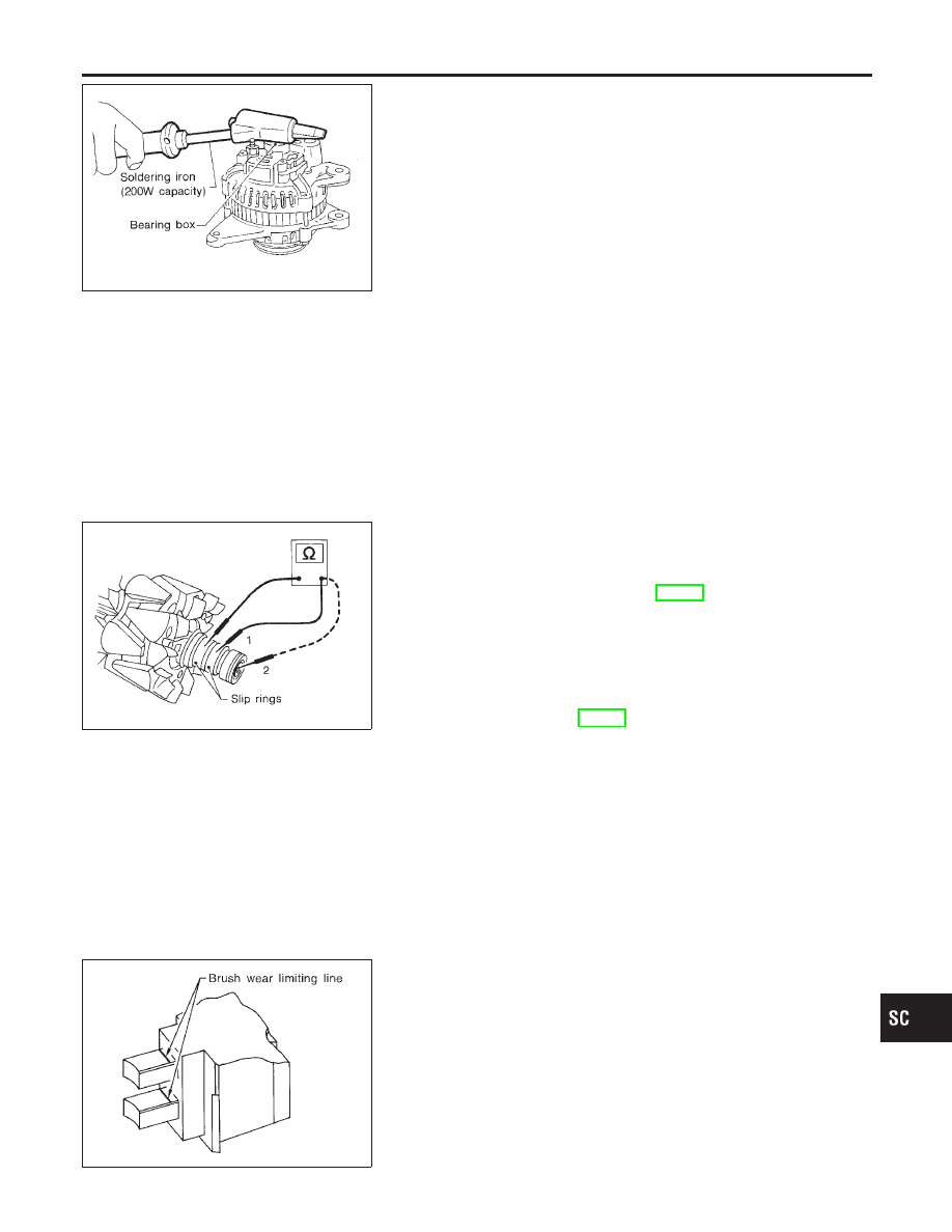
Disassembly
NMSC0021
REAR COVER
NMSC0021S01
CAUTION:
Rear cover may be hard to remove because a ring is used to
lock outer race of rear bearing. To facilitate removal of rear
cover, heat just bearing box section with a 200W soldering
iron.
Do not use a heat gun, as it can damage diode assembly.
REAR BEARING
NMSC0021S02
CAUTION:
I
Do not reuse rear bearing after removal. Replace with a
new one.
I
Do not lubricate rear bearing outer race.
SEL033Z
Inspection
NMSC0022
ROTOR CHECK
NMSC0022S01
1.
Resistance test
Resistance: Refer to SDS (SC-25).
I
Not within the specified values ... Replace rotor.
2.
Insulator test
I
Continuity exists ... Replace rotor.
3.
Check slip ring for wear.
Slip ring minimum outer diameter:
Refer to SDS (SC-25).
I
Not within the specified values ... Replace rotor.
SEL631DA
BRUSH CHECK
NMSC0022S02
1.
Check smooth movement of brush.
I
Not smooth ... Check brush holder and clean.
2.
Check brush for wear.
I
Replace brush if it is worn down to the limit line.
GI
MA
EM
LC
EC
FE
CL
MT
AT
PD
AX
SU
BR
ST
RS
BT
HA
EL
IDX
CHARGING SYSTEM
Disassembly
SC-23