Nissan Silvia. Manual - part 234
SEM936C
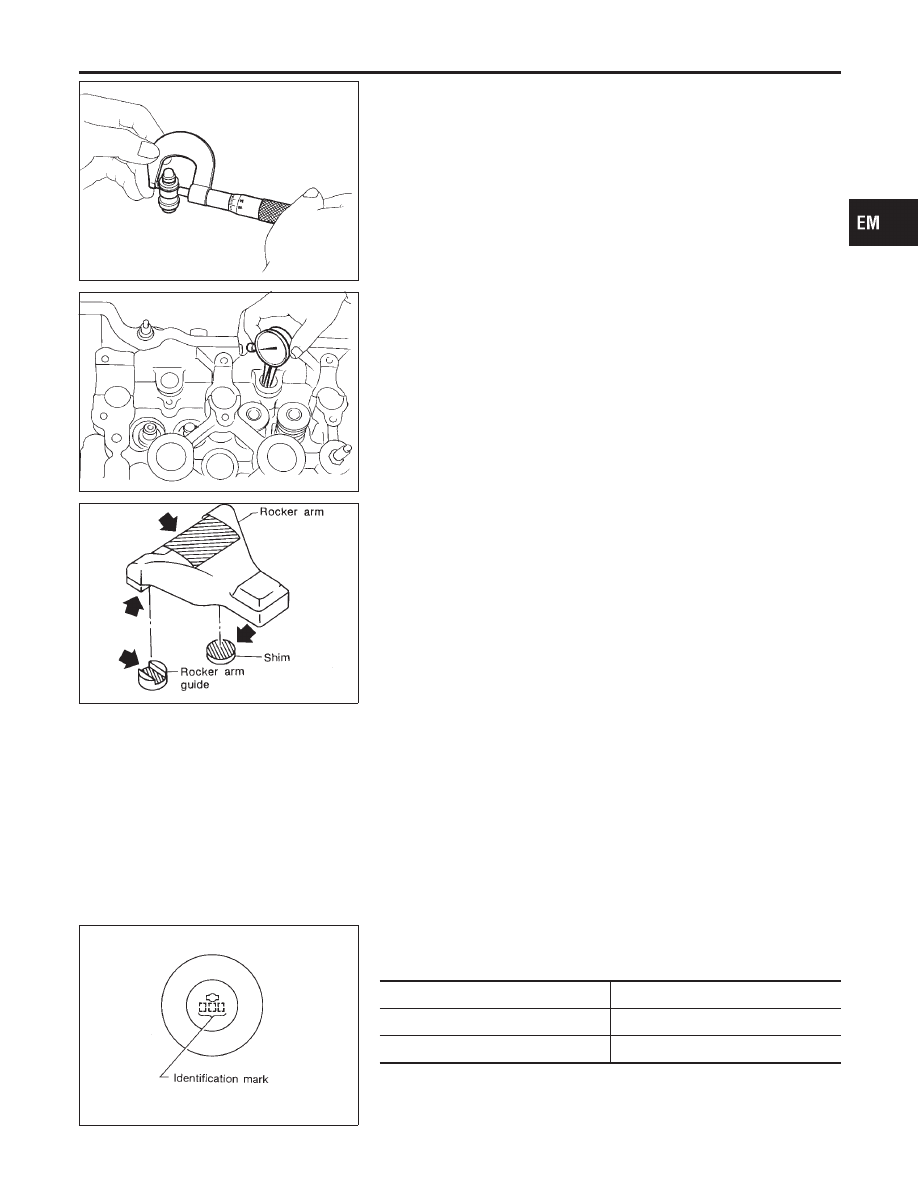
2.
Check diameter of lash adjuster.
Outer diameter:
16.980 - 16.993 mm (0.6685 - 0.6690 in)
SEM084D
3.
Check lash adjuster guide hole diameter.
Inner diameter:
17.000 - 17.020 mm (0.6693 - 0.6701 in)
Standard clearance between lash adjuster and adjuster
guide hole:
0.007 - 0.040 mm (0.0003 - 0.0016 in)
SEM694D
ROCKER ARM, SHIM AND ROCKER ARM GUIDE
NMEM0019S15
Check contact and sliding surfaces of rocker arms, shims and
rocker arm guides for wear or score.
Assembly
NMEM0020
CAUTION:
I
When installing rocker arms, camshaft and oil seal, lubri-
cate contacting surfaces with new engine oil.
I
When tightening cylinder head bolts, camshaft sprocket
bolts and camshaft bracket bolts, lubricate bolt threads
and seat surfaces with new engine oil.
SEM595D
1.
Install valve component parts.
I
Install valves, noting their identification marks as indi-
cated in the table below.
Identification mark
Intake valve
53J
Exhaust valve
5J
GI
MA
LC
EC
FE
CL
MT
AT
PD
AX
SU
BR
ST
RS
BT
HA
SC
EL
IDX
CYLINDER HEAD
Inspection (Cont’d)
EM-49