Nissan Silvia. Manual - part 189
TEL797B
GI
MA
EM
LC
EC
FE
CL
MT
AT
PD
AX
SU
BR
ST
RS
BT
HA
SC
IDX
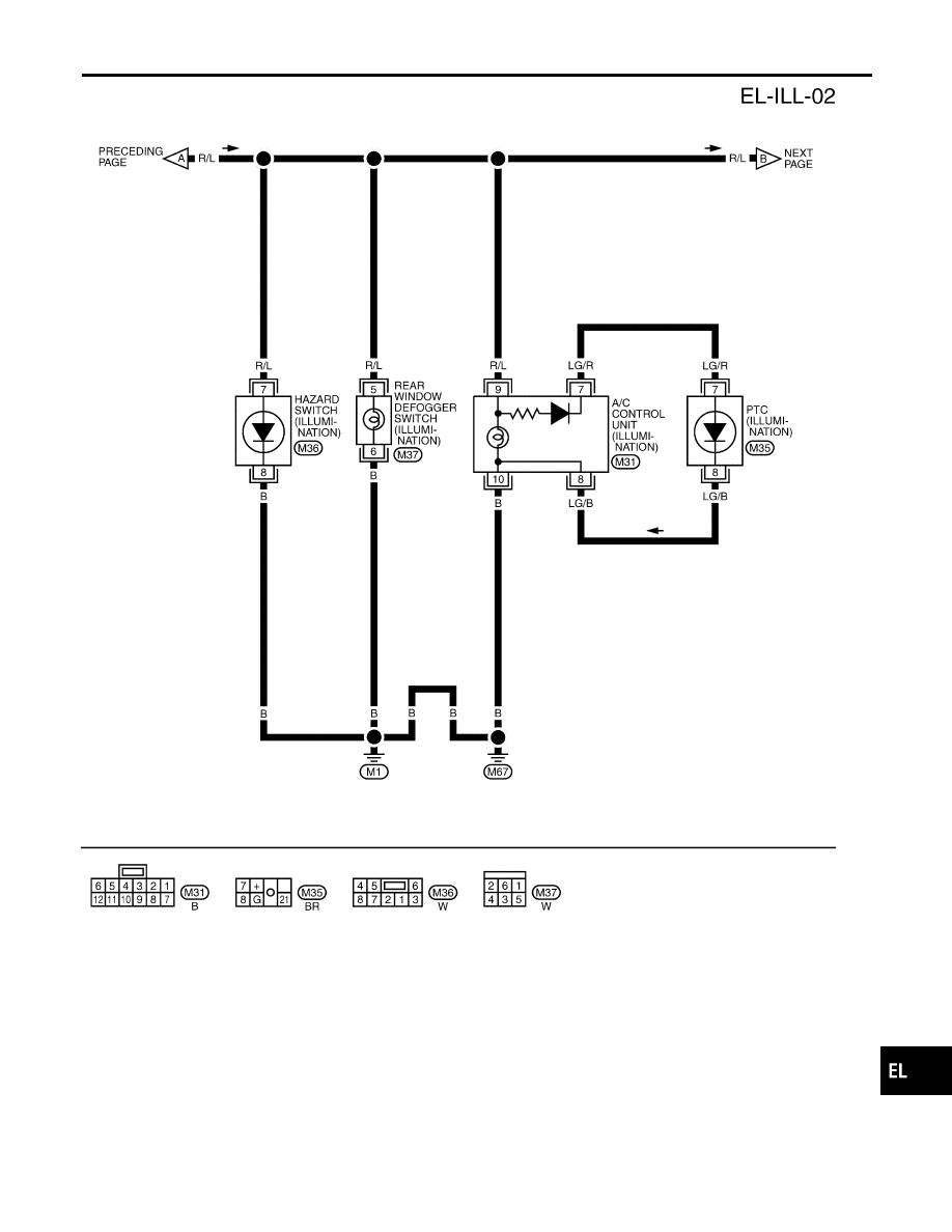
ILLUMINATION
Wiring Diagram — ILL — (Cont’d)
EL-45
|
|
|
TEL797B GI MA EM LC EC FE CL MT AT PD AX SU BR ST RS BT HA SC IDX ILLUMINATION Wiring Diagram — ILL — (Cont’d) EL-45 |