Nissan Silvia. Manual - part 177


  Index      Nissan     Nissan Silvia - Service Manual (2001 year)


Search            


Content   ..  175  176  177  178   ..


Nissan Silvia. Manual - part 177


10

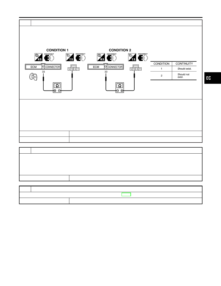
CHECK HEADLAMP INPUT SIGNAL CIRCUIT

A/T models
1. Stop engine.
2. Disconnect ECM harness connector.
3. Disconnect lighting switch harness connector.
4. Check harness continuity between ECM terminal 33 and lighting switch terminal 10 under the following conditions.

SEC431C

5. Also check harness for short to ground and short to power.

M/T models
1. Stop engine.
2. Disconnect ECM harness connector.
3. Disconnect lighting switch harness connector.
4. Check harness continuity between ECM terminal 33 and lighting switch terminal 10. Refer to Wiring Diagram.
5. Also check harness for short to ground and short to power.

OK or NG

OK

©

GO TO 12.

NG

©

GO TO 11.

11

DETECT MALFUNCTIONING PART

Check the following.

I

Harness connectors F4, M60

I

Harness connectors M10, E101

I

Joint connector-1

I

Harness for open and short between ECM and lighting switch

©

Repair open circuit or short to ground or short to power in harness or connectors.

12

CHECK INTERMITTENT INCIDENT

Perform “TROUBLE DIAGNOSIS FOR INTERMITTENT INCIDENT”, EC-82.

©

INSPECTION END

GI

MA

EM

LC

FE

CL

MT

AT

PD

AX

SU

BR

ST

RS

BT

HA

SC

EL

IDX

ELECTRICAL LOAD SIGNAL

Diagnostic Procedure (Cont’d)

EC-223

Wiring Diagram

NMEC0800

TEC822

MI & DATA LINK CONNECTORS

Wiring Diagram

EC-224

Fuel Pressure Regulator

NMEC0801

Fuel pressure at idling
kPa (bar, kg/cm

2

, psi)

Vacuum hose is connected

Approximately 245 (2.45, 2.5, 36)

Vacuum hose is disconnected

Approximately 294 (2.94, 3.0, 43)

Idle Speed and Ignition Timing

NMEC0802

Target idle speed*1

rpm

No-load*3 (in “P” or “N” position)

800

±

50

Air conditioner: ON

rpm

In “P” or “N” position

800

±

50

Ignition timing*2

In “P” or “N” position

15°

±

2° BTDC

Throttle position sensor idle position

V

0.15 - 0.85

*1: Throttle position sensor harness connector connected
*2: Throttle position sensor harness connector disconnected
*3: Under the following conditions:

I

Air conditioner switch: OFF

I

Electrical load: OFF (Lights & rear window defogger)

I

Steering wheel: Kept in straight-ahead position

Mass Air Flow Sensor

NMEC0804

Supply voltage

V

Battery voltage (11 - 14)

Output voltage

V

0.8 - 1.5

Engine Coolant Temperature Sensor

NMEC0805

Temperature

°C (°F)

Resistance

k

20 (68)

2.1 - 2.9

50 (122)

0.68 - 1.00

90 (194)

0.236 - 0.260

Fuel Pump

NMEC0808

Resistance [at 25°C (77°F)]

0.2 - 5.0

IACV-AAC Valve

NMEC0809

Resistance [at 20°C (68°F)]

Approximately 10

Injector

NMEC0810

Resistance [at 20°C (68°F)]

Approximately 11

Throttle Position Sensor

NMEC0812

Throttle valve conditions

Voltage (at normal operating temperature, engine off, ignition switch ON,

throttle opener disengaged)

Completely closed (a)

0.15 - 0.85V

Partially open

Between (a) and (b)

Completely open (b)

3.5 - 4.7V

Heated Oxygen Sensor 1 (Front) Heater

NMEC0813

Resistance [at 25°C (77°F)]

2.3 - 4.3

GI

MA

EM

LC

FE

CL

MT

AT

PD

AX

SU

BR

ST

RS

BT

HA

SC

EL

IDX

SERVICE DATA AND SPECIFICATIONS (SDS)

Fuel Pressure Regulator

EC-225

NOTES


Content   ..  175  176  177  178   ..