Nissan Silvia. Manual - part 157
SEC448C
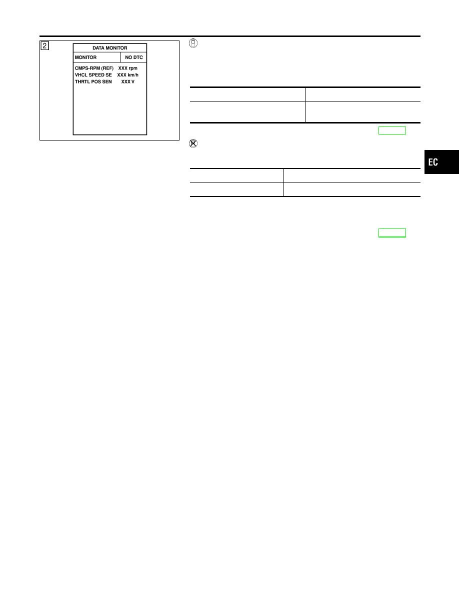
With CONSULT-II
1)
Turn ignition switch “ON” and select “DATA MONITOR” mode
with CONSULT-II.
2)
Start engine and maintain the following conditions for at least
5 consecutive seconds.
VHCL SPEED SE
More than 4 km/h (2 MPH)
Selector lever
Suitable position except “P” or “N”
position
3)
If DTC is detected, go to “Diagnostic Procedure”, EC-145.
Without CONSULT-II
1)
Start engine and maintain the following conditions for at least
5 consecutive seconds.
Vehicle speed
More than 4 km/h (2 MPH)
Selector lever
Suitable position except “P” or “N” position
2)
Turn ignition switch “OFF” and wait at least 5 seconds.
3)
Turn ignition switch “ON” and perform “Diagnostic Test Mode
II (Self-diagnostic results)” with ECM.
4)
If DTC is detected, go to “Diagnostic Procedure”, EC-145.
GI
MA
EM
LC
FE
CL
MT
AT
PD
AX
SU
BR
ST
RS
BT
HA
SC
EL
IDX
DTC 0403 THROTTLE POSITION SENSOR
DTC Confirmation Procedure (Cont’d)
EC-143