Nissan Silvia. Manual - part 128
SRS928
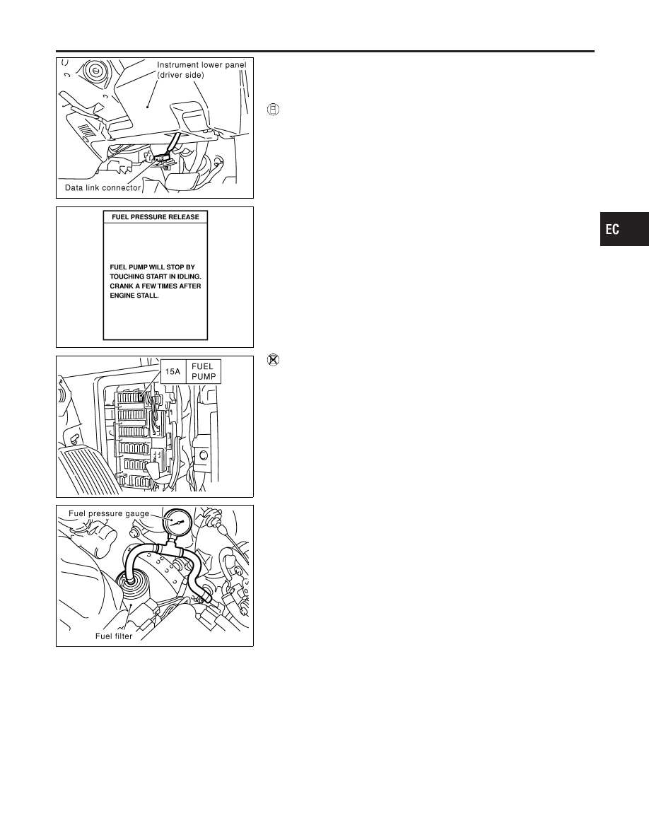
SEF214Y
Fuel Pressure Release
NMEC0023
Before disconnecting fuel line, release fuel pressure from fuel
line to eliminate danger.
WITH CONSULT-II
NMEC0023S01
1.
Turn ignition switch “ON”.
2.
Perform “FUEL PRESSURE RELEASE” in “WORK SUP-
PORT” mode with CONSULT-II.
3.
Start engine.
4.
After engine stalls, crank it two or three times to release all fuel
pressure.
5.
Turn ignition switch “OFF”.
SEC323C
WITHOUT CONSULT-II
NMEC0023S02
1.
Remove fuel pump fuse located in fuse box.
2.
Start engine.
3.
After engine stalls, crank it two or three times to release all fuel
pressure.
4.
Turn ignition switch “OFF”.
5.
Reinstall fuel pump fuse after servicing fuel system.
SEC324C
Fuel Pressure Check
NMEC0024
I
When reconnecting fuel line, always use new clamps.
I
Make sure that clamp screw does not contact adjacent
parts.
I
Use a torque driver to tighten clamps.
I
Use Pressure Gauge to check fuel pressure.
I
Do not perform fuel pressure check with system operat-
ing. Fuel pressure gauge may indicate false readings.
1.
Release fuel pressure to zero.
2.
Disconnect fuel hose from fuel filter.
3.
Install pressure gauge between fuel hose and fuel filter.
4.
Start engine and check for fuel leakage.
5.
Read the indication of fuel pressure gauge.
At idling:
With vacuum hose connected
Approximately 235 kPa (2.4 kg/cm
2
, 34 psi)
With vacuum hose disconnected
Approximately 294 kPa (3.0 kg/cm
2
, 43 psi)
If results are unsatisfactory, perform Fuel Pressure Regulator
Check.
GI
MA
EM
LC
FE
CL
MT
AT
PD
AX
SU
BR
ST
RS
BT
HA
SC
EL
IDX
BASIC SERVICE PROCEDURE
Fuel Pressure Release
EC-27