Nissan Silvia. Manual - part 118
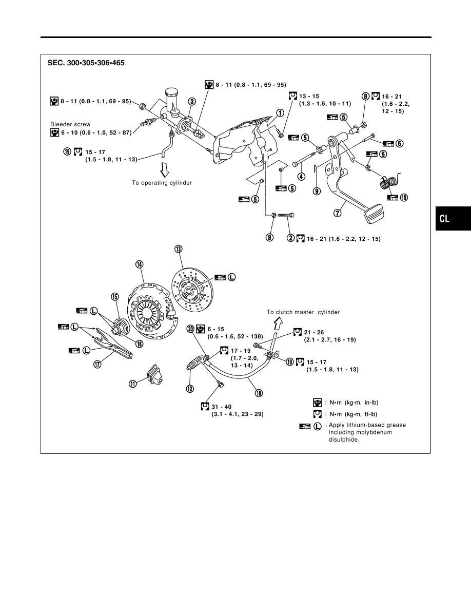
Components
NMCL0004
SCL876
1.
Clutch pedal bracket
2.
Stopper bolt
3.
Clutch master cylinder
4.
Fulcrum pin
5.
Bushing
6.
Clevis pin
7.
Clutch pedal
8.
Lock nut
9.
Snap pin
10. Assist spring
11. Dust boot
12. Operating cylinder
13. Clutch disc
14. Clutch cover
15. Release bearing
16. Release bearing sleeve
17. Withdrawal lever
18. Clutch hose
19. Flare nut
20. Air bleeder
GI
MA
EM
LC
EC
FE
MT
AT
PD
AX
SU
BR
ST
RS
BT
HA
SC
EL
IDX
CLUTCH SYSTEM — HYDRAULIC TYPE
Components
CL-5