Nissan Silvia. Manual - part 102
 

  Index      Nissan     Nissan Silvia - Service Manual (2001 year)


Search            


Content   ..  100  101  102  103   ..


Nissan Silvia. Manual - part 102


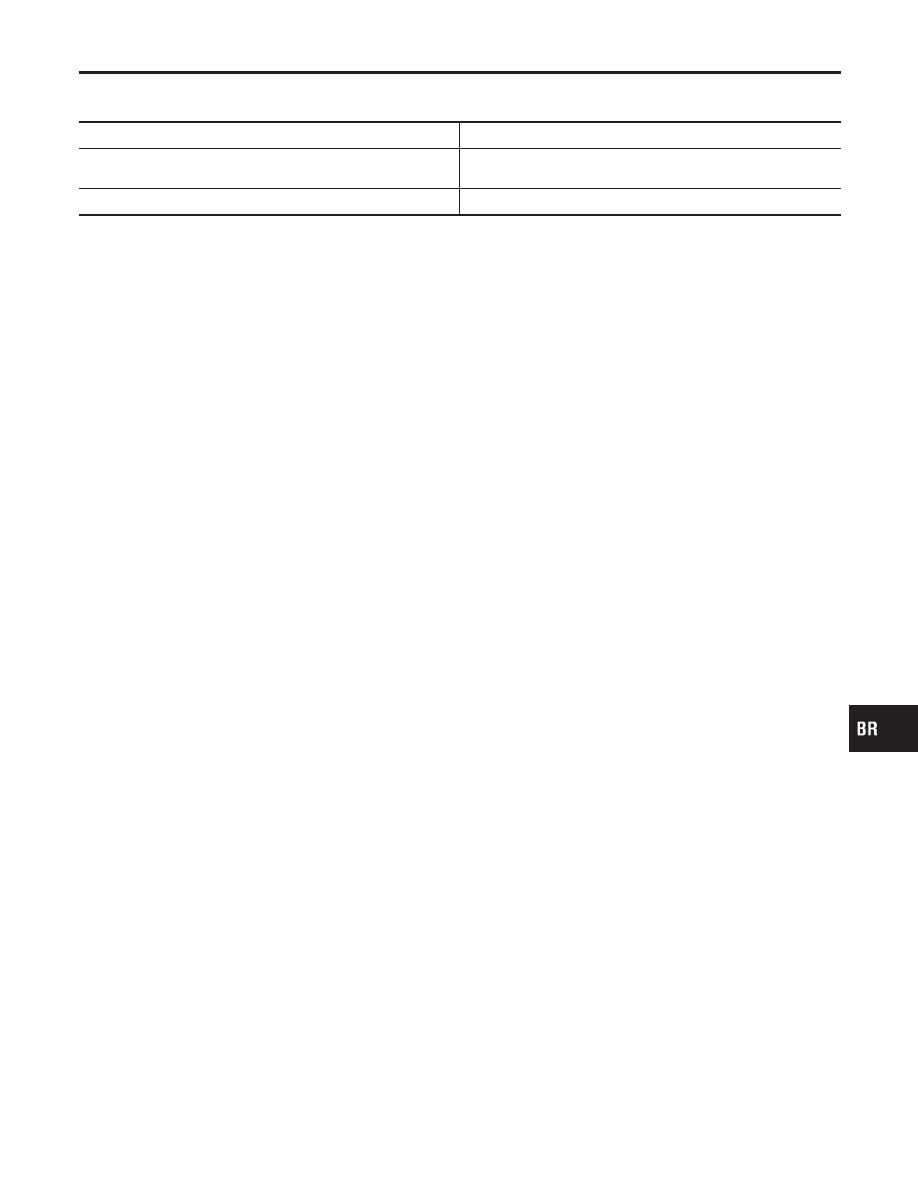
Parking Brake Control

NMBR0084

Unit: notch

Control Type

Center lever

Lever stroke
[under force of 196 N (20 kg, 44 lb)]

7 - 9

Lever stroke when warning switch comes on

1 or less

GI

MA

EM

LC

EC

FE

CL

MT

AT

PD

AX

SU

ST

RS

BT

HA

SC

EL

IDX

SERVICE DATA AND SPECIFICATIONS (SDS)

Parking Brake Control

BR-91

NOTES

BODY & TRIM

SECTION

BT

CONTENTS

PRECAUTIONS ...............................................................2

Service Notice..............................................................2
Supplemental Restraint System (SRS)

AIR

BAG

............................................................................2

Maintenance ................................................................2

CLIP AND FASTENER....................................................3

Description ...................................................................3

BODY FRONT END.........................................................6

Removal and Installation .............................................6

FRONT BUMPER ASSEMBLY

....................................6

BODY REAR END AND OPENER................................10

Removal and Installation ...........................................10

REAR BUMPER ASSEMBLY

....................................10

DOOR.............................................................................13

Adjustment .................................................................13

STRIKER ADJUSTMENT

..........................................13

Door Glass.................................................................14

DOOR GLASS AND REGULATOR

............................14

Door Glass Fitting Adjustment...................................16

IN-OUT ADJUSTMENT (AT THE GLASS WAIST)

.......17

FORE-AFT TILT ADJUSTMENT

................................17

IN-OUT TILT ADJUSTMENT (AT GLASS UPPER
STOP)

.....................................................................17

UP-STOP ADJUSTMENT

..........................................18

FORE-AFT ADJUSTMENT

........................................18

Door Limit Switch Reset (Driver side only) ...............19

RESET CONDITIONS

..............................................19

RESET PROCEDURES

............................................19

Door Lock ..................................................................20

BELL CRANK ADJUSTMENT

....................................20

OUTSIDE HANDLE ROD ADJUSTMENT

...................20

REMOVAL

...............................................................21

INSTRUMENT PANEL ASSEMBLY .............................22

Removal and Installation ...........................................22

SIDE AND FLOOR TRIM...............................................26

Removal and Installation ...........................................26

DOOR TRIM ...................................................................29

Removal and Installation ...........................................29

ROOF TRIM ...................................................................31

Removal and Installation ...........................................31

TRUNK ROOM TRIM .....................................................33

Removal and Installation ...........................................33

EXTERIOR .....................................................................34

Removal and Installation ...........................................34

FRONT SEAT ................................................................38

Removal and Installation ...........................................38

REAR SEAT...................................................................39

Removal and Installation ...........................................39

SUNROOF......................................................................40

Adjustment .................................................................40
Removal.....................................................................40
Trouble Diagnoses.....................................................44

DIAGNOSTIC TABLE

................................................44

WIND DEFLECTOR

.................................................44

ADJUSTMENT

.........................................................45

DRAIN HOSES

........................................................46

WEATHERSTRIP

.....................................................47

LINK AND WIRE ASSEMBLY

....................................47

WINDSHIELD AND WINDOWS ....................................48

Removal and Installation ...........................................48

REMOVAL

...............................................................48

INSTALLATION

........................................................48

WINDSHIELD AND WINDOWS

.................................49

DOOR MIRROR .............................................................52

Removal and Installation ...........................................52

BODY (ALIGNMENT) ....................................................53

Alignment ...................................................................53

ENGINE COMPARTMENT

........................................54

UNDERBODY

..........................................................56

GI

MA

EM

LC

EC

FE

CL

MT

AT

PD

AX

SU

BR

ST

RS

HA

SC

EL

IDX

Service Notice

NMBT0001

I

When removing or installing various parts, place a cloth or padding onto the vehicle body to prevent
scratches.

I

Handle trim, molding, instruments, grille, etc. carefully during removing or installing. Be careful not to soil
or damage them.

I

Apply sealing compound where necessary when installing parts.

I

When applying sealing compound, be careful that the sealing compound does not protrude from parts.

I

When replacing any metal parts (for example body outer panel, members, etc.), be sure to take rust pre-
vention measures.

Supplemental Restraint System (SRS) “AIR
BAG”

NMBT0002

The Supplemental Restraint System such as “AIR BAG” and “SEAT BELT PRE-TENSIONER” used along with
a seat belt, helps to reduce the risk or severity of injury to the driver and front passenger for certain types of
collision. The SRS system composition which is available to NISSAN MODEL S15 is as follows:
The Supplemental Restraint System consists of driver air bag module (located in the center of the steering
wheel), front passenger air bag module (located on the instrument panel on passenger side), a diagnosis
sensor unit, warning lamp, wiring harness and spiral cable.
Information necessary to service the system safely is included in the RS section of this Service Manual.

WARNING:

I

To avoid rendering the SRS inoperative, which could increase the risk of personal injury or death
in the event of a collision which would result in air bag inflation, all maintenance should be per-
formed by an authorized NISSAN dealer.

I

Improper maintenance, including incorrect removal and installation of the SRS, can lead to per-
sonal injury caused by unintentional activation of the system. For removal of Spiral Cable and Air
Bag Module, see the RS section.

I

Do not use electrical test equipment on any circuit related to the SRS unless instructed to in this
Service Manual. SRS wiring harnesses can be identified with yellow harness connector.

Maintenance

NMBT0035

MMA093A

PRECAUTIONS

Service Notice

BT-2


Content   ..  100  101  102  103   ..