Nissan Silvia. Manual - part 57
SAT043B
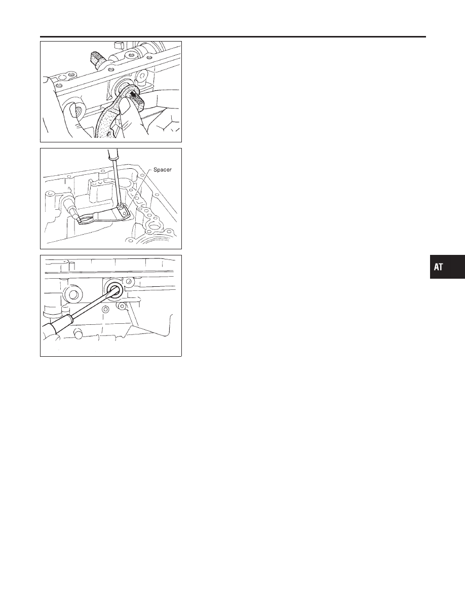
d.
Remove manual shaft from transmission case.
SAT934A
e.
Remove spacer and detent spring from transmission case.
SAT044B
f.
Remove oil seal from transmission case.
GI
MA
EM
LC
EC
FE
CL
MT
PD
AX
SU
BR
ST
RS
BT
HA
SC
EL
IDX
DISASSEMBLY
AT-225