Nissan Silvia. Manual - part 13
SAT514G
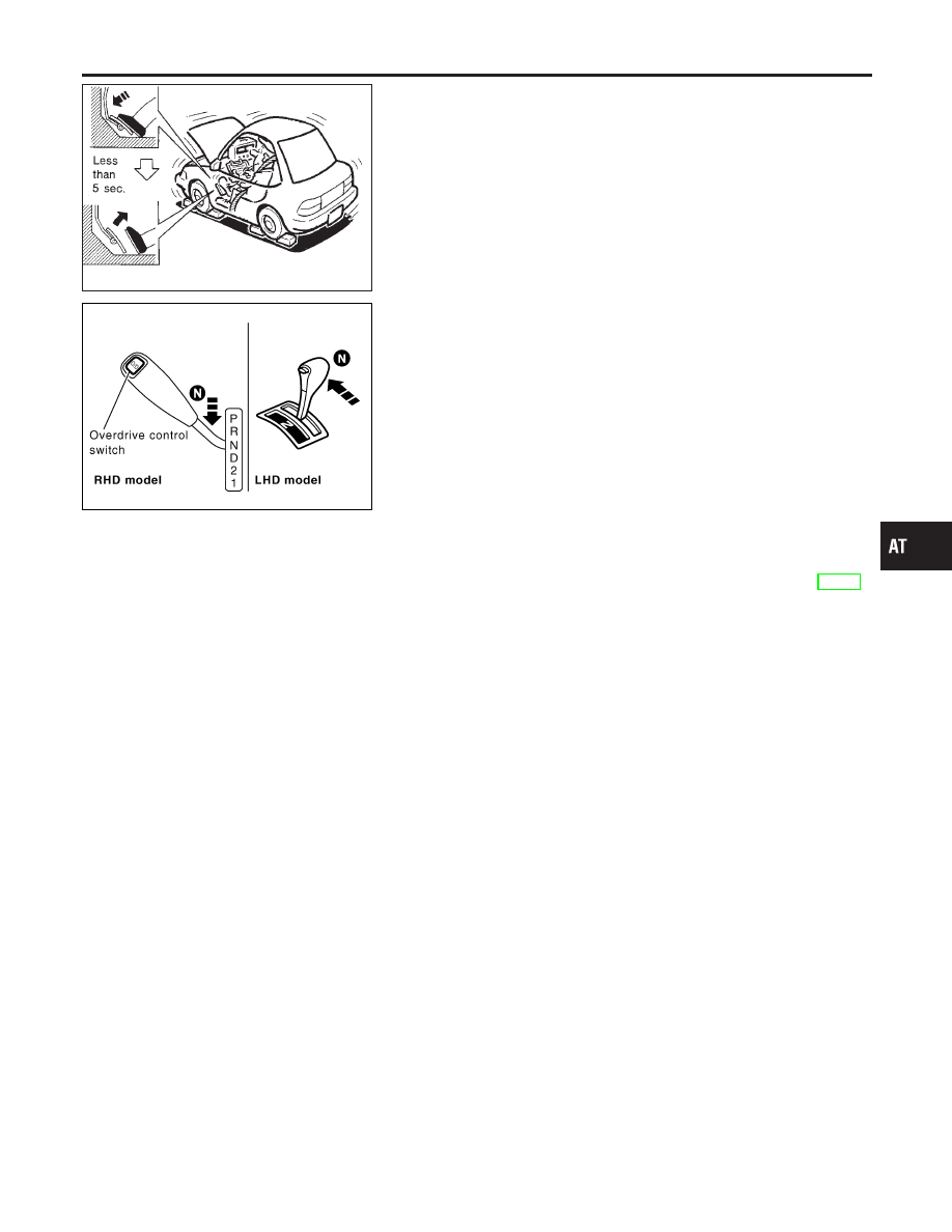
5.
Start engine, apply foot brake, and place selector lever in “D”
position.
6.
Accelerate to wide open throttle gradually while applying foot
brake.
7.
Quickly note the engine stall revolution and immediately
release throttle.
I
During test, never hold throttle wide open for more than 5
seconds.
Stall revolution:
2,725 - 2,975 rpm
SAT786J
8.
Move selector lever to “N” position.
9.
Cool off ATF.
I
Run engine at idle for at least one minute.
10. Repeat steps 5 through 9 with selector lever in “2”, “1” and “R”
positions.
JUDGEMENT OF STALL TEST
NMAT0022S02
The test result and possible damaged components relating to each
result are shown in the illustration. In order to pinpoint the possible
damaged components, follow the WORK FLOW shown in AT-46.
NOTE:
Stall revolution is too high in “D” or “2” position:
I
Slippage occurs in 1st gear but not in 2nd and 3rd gears. .....
Low one-way clutch slippage
I
Slippage occurs at the following gears:
1st through 3rd gears in “D” position and engine brake func-
tions.
1st and 2nd gears in “2” position and engine brake functions
with accelerator pedal released (fully closed throttle). ..... For-
ward clutch or forward one-way clutch slippage
Stall revolution is too high in “R” position:
I
Engine brake does not function in “1” position. ..... Low &
reverse brake slippage
I
Engine brake functions in “1” position. ..... Reverse clutch slip-
page
Stall revolution within specifications:
I
Vehicle does not achieve speed of more than 80 km/h (50
MPH). ..... One-way clutch seizure in torque converter housing
CAUTION:
Be careful since automatic fluid temperature increases abnor-
mally.
I
Slippage occurs in 3rd and 4th gears in “D” position. ..... High
clutch slippage
I
Slippage occurs in 2nd and 4th gear in “D” position. ..... Brake
band slippage
Stall revolution less than specifications:
I
Poor acceleration during starts. ..... One-way clutch seizure in
torque converter
GI
MA
EM
LC
EC
FE
CL
MT
PD
AX
SU
BR
ST
RS
BT
HA
SC
EL
IDX
TROUBLE DIAGNOSIS — BASIC INSPECTION
Stall Test (Cont’d)
AT-49