Nissan Almera Tino V10. Manual - part 531
EC-950
[YD (WITH EURO-OBD)]
ENGINE CONTROL SYSTEM
System Chart
EBS0137S
*1: The input signal is sent to the ECM through CAN communication line.
*2: The output signal is sent from the ECM through CAN communication line.
*3: For YD22DDTi engine models
Fuel Injection Control System
EBS0137T
SYSTEM DESCRIPTION
Three types of fuel injection control are provided to accommodate engine operating conditions; normal control,
idle control and start control. The ECM determines the appropriate fuel injection control. Under each control,
the amount of fuel injected is adjusted to improve engine performance.
Pulse signals are sent to fuel injectors according to the input signals to adjust the amount of fuel injected to
preset value.
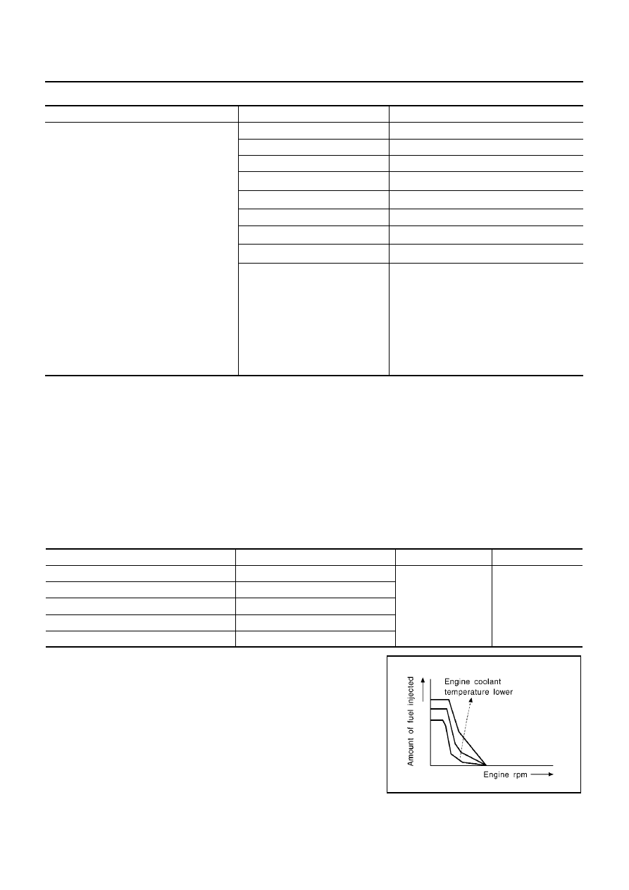
START CONTROL
Input/Output Signal Chart
When the ECM receives a start signal from the ignition switch, the
ECM adapts the fuel injection system for the start control. The
amount of fuel injected at engine starting is a preset program value
in the ECM. The program is determined by the engine speed, engine
coolant temperature and fuel rail pressure.
For better startability under cool engine conditions, the lower the
coolant temperature becomes, the greater the amount of fuel
injected. The ECM ends the start control when the engine speed
reaches the specific value, and shifts the control to the normal or idle
control.
Input (Sensor)
ECM Function
Output (Actuator)
●
Accelerator pedal position sensor
●
Fuel rail pressure sensor
●
Fuel pump temperature sensor
●
Engine coolant temperature sensor
●
Mass air flow sensor
●
Intake air temperature sensor
●
Crankshaft position sensor
●
Camshaft position sensor
●
Turbocharger boost sensor*
3
●
Vehicle speed sensor*
1
●
ESP/TCS/ABS control unit*
1
●
Ignition switch
●
Stop lamp switch
●
Air conditioner switch*
1
●
Park/neutral position switch
●
Battery voltage
●
Power steering pressure switch
Fuel injection control
Fuel injector and Fuel pump
Fuel injection timing control
Fuel injector and Fuel pump
Fuel cut control
Fuel injector and Fuel pump
Glow control system
Glow relay and glow indicator lamp*
2
On board diagnostic system
Malfunction indicator (MI)*
2
EGR volume control
EGR volume control valve
Cooling fan control
Cooling fan relay*
2
Turbocharger boost control*
3
Turbocharger boost control solenoid valve*
3
Air conditioning cut control
Air conditioner relay*
2
Sensor
Input Signal to ECM
ECM Function
Actuator
Engine coolant temperature sensor
Engine coolant temperature
Fuel injection control
(start control)
Fuel injector
Fuel pump
Crankshaft position sensor
Engine speed
Camshaft position sensor
Piston position
Ignition switch
Start signal
Fuel rail pressure sensor
Fuel rail pressure
SEF648S