Nissan Almera Tino V10. Manual - part 426


  Index      Nissan     Nissan Almera Tino V10 - Service Manual (2003 year)


Search            


Content   ..  424  425  426  427   ..


Nissan Almera Tino V10. Manual - part 426


EC-530

[QG (WITH EURO-OBD)]

FUEL PUMP CIRCUIT

FUEL PUMP CIRCUIT

PFP:17042

Description

EBS00QTI

SYSTEM DESCRIPTION

*: The ECM determines the start signal status by the signals of engine speed and battery voltage.

The ECM activates the fuel pump for several seconds after the ignition switch is turned on to improve engine
startability. If the ECM receives a engine speed signal from the crankshaft position sensor (POS) and cam-
shaft position sensor (PHASE), it knows that the engine is rotating, and causes the pump to operate. If the
engine speed signal is not received when the ignition switch is ON, the engine stalls. The ECM stops pump
operation and prevents battery discharging, thereby improving safety. The ECM does not directly drive the fuel
pump. It controls the ON/OFF fuel pump relay, which in turn controls the fuel pump.

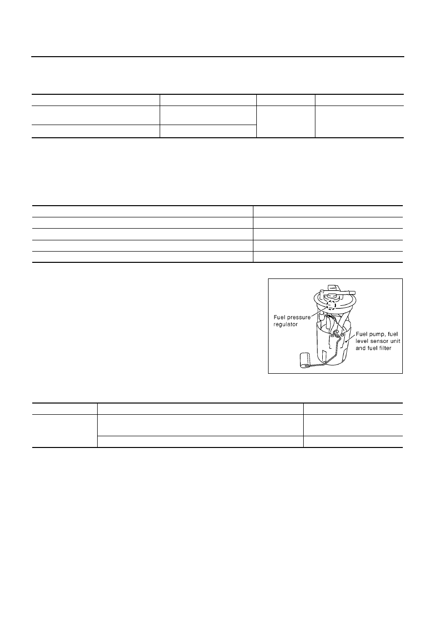
COMPONENT DESCRIPTION

A turbine type design fuel pump is used in the fuel tank.

CONSULT-II Reference Value in Data Monitor Mode

EBS00QTJ

Specification data are reference values.

Sensor

Input Signal to ECM

ECM Function

Actuator

Crankshaft position sensor (POS)
Camshaft position sensor (PHASE)

Engine speed

*

Fuel pump control

Fuel pump relay

Battery

Battery voltage

*

Condition

Fuel pump operation

Ignition switch is turned to ON.

Operates for 1 second.

Engine running and cranking

Operates.

When engine is stopped

Stops in 1.5 seconds.

Except as shown above

Stops.

MBIB0046E

MONITOR ITEM

CONDITION

SPECIFICATION

FUEL PUMP RLY

For 1 seconds after turning ignition switch ON

Engine running or cranking

ON

Except above conditions

OFF

FUEL PUMP CIRCUIT

EC-531

[QG (WITH EURO-OBD)]

C

D

E

F

G

H

I

J

K

L

M

A

EC

Wiring Diagram

EBS00QTK

YEC475A

EC-532

[QG (WITH EURO-OBD)]

FUEL PUMP CIRCUIT

Specification data are reference values and are measured between each terminal and ground.

CAUTION:

Do not use ECM ground terminals when measuring input/output voltage. Doing so may result in dam-
age to the ECM's transistor. Use a ground other than ECM terminals, such as the ground.

Diagnostic Procedure

EBS00QTL

1.

CHECK OVERALL FUNCTION

1.

Turn ignition switch “ON”.

2.

Pinch fuel feed hose with two fingers.
Fuel pressure pulsation should be felt on the fuel hose for 1
second after ignition switch is turned “ON”.

OK or NG

OK

>> INSPECTION END

NG

>> GO TO 2.

2.

CHECK FUEL PUMP RELAY POWER SUPPLY CIRCUIT

1.

Turn ignition switch “OFF”.

2.

Disconnect fuel pump relay.

3.

Turn ignition switch “ON”.

4.

Check voltage between fuel pump relay terminals 1, 5 and
ground with CONSULT-II or tester.

OK or NG

OK

>> GO TO 4.

NG

>> GO TO 3.

TER-

MINAL

NO.

WIRE

COLOR

ITEM

CONDITION

DATA (DC Voltage)

113

B/P

Fuel pump relay

[Ignition switch “ON”]

For 1 seconds after turning ignition switch “ON”

[Engine is running]

0 - 1.0V

[Ignition switch “ON”]

More than 1 seconds after turning ignition switch
“ON”.

BATTERY VOLTAGE
(11 - 14V)

MBIB0114E

MBIB1001E

Voltage: Battery voltage

MBIB0191E

FUEL PUMP CIRCUIT

EC-533

[QG (WITH EURO-OBD)]

C

D

E

F

G

H

I

J

K

L

M

A

EC

3.

DETECT MALFUNCTIONING PART

Check the following.

Fuse block (J/B) connector B1

10A fuse

15A fuse

Harness for open or short between fuel pump relay and fuse

>> Repair open circuit or short to ground or short to power in harness or connectors.

4.

CHECK FUEL PUMP POWER SUPPLY AND GROUND CIRCUIT FOR OPEN AND SHORT

1.

Turn ignition switch “OFF”.

2.

Disconnect fuel level sensor unit and fuel pump harness con-
nector.

3.

Check harness continuity between fuel pump relay terminal 3
and fuel level sensor unit and fuel pump terminal 5, fuel level
sensor unit and fuel pump terminal 3 and body ground.
Refer to Wiring Diagram.

4.

Also check harness for short to ground and short to power.

OK or NG

OK

>> GO TO 6.

NG

>> GO TO 5.

5.

DETECT MALFUNCTIONING PART

Check the following.

Harness connectors B36, D81

Harness for open or short between fuel level sensor unit and fuel pump and fuel pump relay

Harness for open or short between fuel level sensor unit and fuel pump and body ground

>> Repair open circuit or short to ground or short to power in harness or connectors.

6.

CHECK FUEL PUMP RELAY OUTPUT SIGNAL CIRCUIT FOR OPEN AND SHORT

1.

Disconnect ECM harness connector.

2.

Check harness continuity between ECM terminal 113 and fuel pump relay terminal 2.
Refer to Wiring Diagram.

3.

Also check harness for short to ground and short to power.

OK or NG

OK

>> GO TO 8.

NG

>> GO TO 7.

7.

DETECT MALFUNCTIONING PART

Check the following.

Harness connectors M12, B5 (LHD models)

Harness connectors M65, B42 (RHD models)

Harness for open or short between ECM and fuel pump relay

>> Repair open circuit or short to ground or short to power in harness or connectors.

Continuity should exist.

MBIB0115E

Continuity should exist.


Content   ..  424  425  426  427   ..