Nissan Pathfinder. Manual - part 551
ROCKER COVER
EM-43
< REMOVAL AND INSTALLATION >
C
D
E
F
G
H
I
J
K
L
M
A
EM
N
P
O
ROCKER COVER
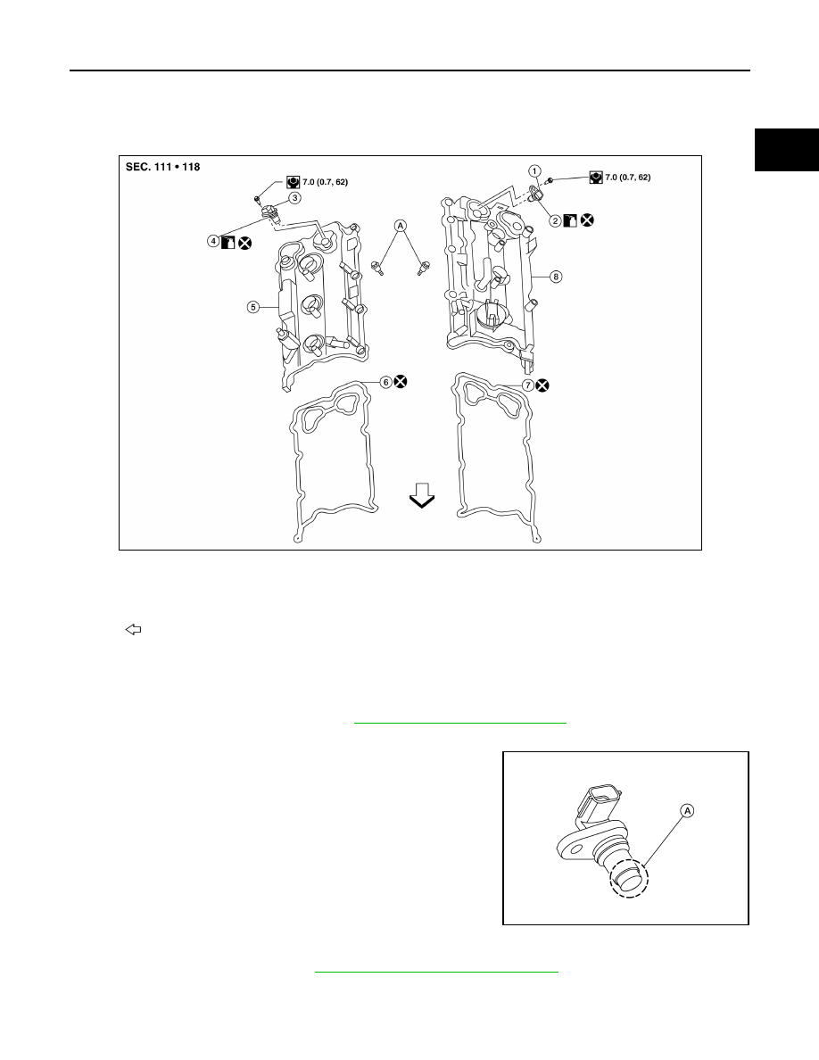
Exploded View
INFOID:0000000009177913
Removal and Installation (LH)
INFOID:0000000009177914
REMOVAL
1. Remove the engine room cover. Refer to
EM-23, "Removal and Installation"
2. Remove blow by hose from rocker cover.
3. Remove camshaft position sensor.
CAUTION:
• Handle carefully to avoid dropping and shocks.
• Do not disassemble.
• Do not allow metal powder to adhere to magnetic part at
sensor tip (A).
• Do not place sensor in a location where they are exposed
to magnetism.
4. Unclip the camshaft position sensor harness connectors.
5. Remove the ignition coils. Refer to
EM-42, "Removal and Installation (LH)"
.
CAUTION:
Do not shock ignition coils.
1.
Camshaft position sensor (LH)
2.
O-ring
3.
Camshaft position sensor (RH)
4.
O-ring
5.
Rocker cover (RH)
6.
Rocker cover gasket (RH)
7.
Rocker cover gasket (LH)
8.
Rocker cover (LH)
A. Follow installation procedure
Engine front
AWBIA1231GB
ALBIA0258ZZ