Nissan Pathfinder. Manual - part 146
AV
DIAGNOSIS SYSTEM (AV CONTROL UNIT)
AV-411
< SYSTEM DESCRIPTION >
[PREMIUM AUDIO WITH NAVIGATION]
C
D
E
F
G
H
I
J
K
L
M
B
A
O
P
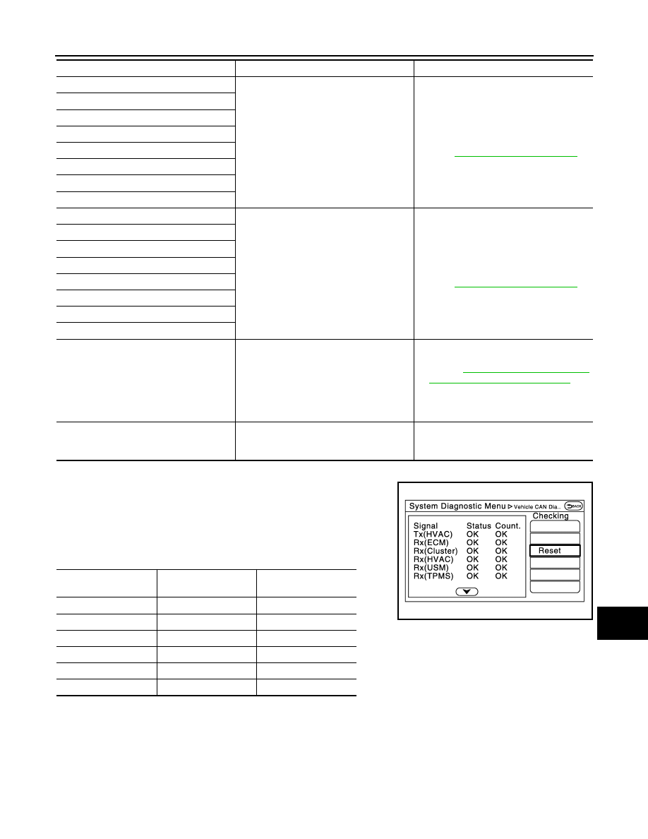
Vehicle CAN Diagnosis
• CAN communication status and error counter is displayed.
• The error counter displays “OK” if any malfunction was not
detected in the past and displays “0” if a malfunction is detected. It
increases by 1 if the condition is normal at the next ignition switch
ON cycle. The upper limit of the counter is 39.
• The error counter is erased if “Reset” is pressed.
NOTE:
“???” indicates UNKWN.
AV COMM Diagnosis
Left Front: open
Malfunction is detected in sound signal cir-
cuits between BOSE speaker amp. and
front door speaker.
Sound signal circuits between BOSE
speaker amp. and front door speaker.
Refer to
.
Left Front: short
Left Front: short to ground
Left Front: short to battery
Right Front: open
Right Front: short
Right Front: short to ground
Right Front: short to battery
Left Rear: open
Malfunction is detected in sound signal cir-
cuits between BOSE speaker amp. and
rear door speaker.
Sound signal circuits between BOSE
speaker amp. and rear door speaker.
Refer to
.
Left Rear: short
Left Rear: short to ground
Left Rear: short to battery
Right Rear: open
Right Rear: short
Right Rear: short to ground
Right Rear: short to battery
• AV COMM CIRCUIT
• Switches Connection Error
When one of the following is detected:
• malfunction is detected in A/C and AV
switch assembly power supply and
ground circuits.
• malfunction is detected in AV communi-
cation circuits between AV control unit
and A/C and AV switch assembly.
• A/C and AV switch assembly power sup-
ply or ground circuit.
Refer to
ASSEMBLY : Diagnosis Procedure"
.
• AV communication circuits between AV
control unit and A/C and AV switch as-
sembly.
• AV COMM CIRCUIT
• Switches Connection Error
• 2nd Display Connection Error
Malfunction is detected in AV communica-
tion circuits between AV control unit and A/
C and AV switch assembly.
AV communication circuits between AV
control unit and A/C and AV switch assem-
bly.
Error item
Description
Possible malfunction factor/Action to take
Items
Display (Current)
Malfunction counter
(Past)
Tx(HVAC)
OK / ???
OK / 0 – 39
Rx(ECM)
OK / ???
OK / 0 – 39
Rx(Cluster)
OK / ???
OK / 0 – 39
Rx(HVAC)
OK / ???
OK / 0 – 39
Rx(USM)
OK / ???
OK / 0 – 39
Rx(TPMS)
OK / ???
OK / 0 – 39
JSNIA2391ZZ