Content .. 1200 1201 1202 1203 ..
Nissan Pathfinder. Manual - part 1202
WCS
DIAGNOSIS AND REPAIR WORKFLOW
WCS-25
< BASIC INSPECTION >
C
D
E
F
G
H
I
J
K
L
M
B
A
O
P
BASIC INSPECTION
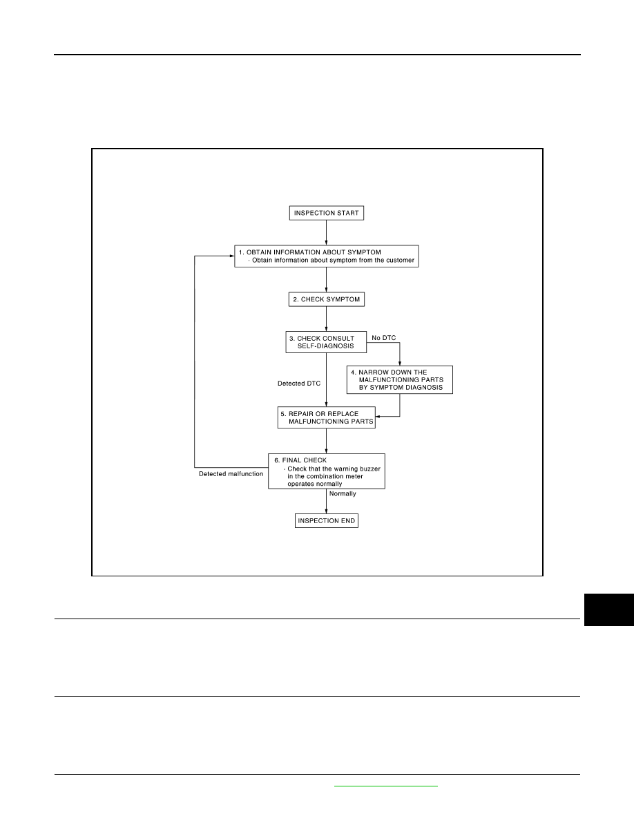
DIAGNOSIS AND REPAIR WORKFLOW
Work Flow
INFOID:0000000009174322
OVERALL SEQUENCE
DETAILED FLOW
1.
OBTAIN INFORMATION ABOUT SYMPTOM
Interview the customer to obtain as much information as possible about the conditions and environment under
which the malfunction occurred.
>> GO TO 2.
2.
CHECK SYMPTOM
• Check the symptom based on the information obtained from the customer.
• Check if any other malfunctions are present.
>> GO TO 3.
3.
CHECK CONSULT SELF-DIAGNOSIS RESULTS
Connect CONSULT and perform Self Diagnosis. Refer to
AWNIA2375GB