Nissan Pathfinder. Manual - part 1142


  Index      Nissan     Nissan Pathfinder (2014 year) - Service and Repair Manual


Search            


Content   ..  1140  1141  1142  1143   ..


Nissan Pathfinder. Manual - part 1142


STRUCTURE AND OPERATION

TM-27

< SYSTEM DESCRIPTION >

[CVT: RE0F10E]

C

E

F

G

H

I

J

K

L

M

A

B

TM

N

O

P

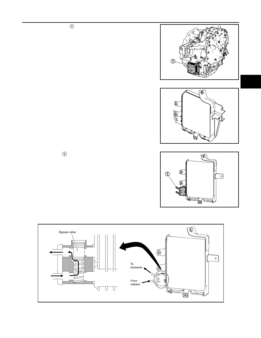
• The CVT oil warmer   is installed on the front part of transaxle

assembly.

• When engine is started while engine and CVT are cold, engine

coolant temperature rises more quickly than CVT fluid tempera-

ture. CVT oil warmer is provided with two circuits for CVT and

engine coolant respectively so that warmed engine coolant warms

CVT quickly. This helps shorten CVT warming up time, improving

fuel economy.

• A cooling effect is obtained when CVT fluid temperature is high.

CVT Fluid Cooler

• The CVT fluid cooler is installed to the vehicle front LH.

• The CVT fluid cooler prevents CVT fluid temperature from an

abnormal increase while driving the vehicle. When flowing into the

CVT fluid cooler, CVT fluid is cooled by driving blast while driving

the vehicle.

Bypass Valve

• The bypass valve   is installed to the CVT fluid cooler.

• Bypass valve controls CVT fluid flow.

• When CVT fluid temperature is low, the bypass valve is open. Most of CVT fluid therefore returns to the tran-

saxle without flowing into the cooler core that has larger flow resistance.

JSDIA4001ZZ

JSDIA4002ZZ

JSDIA4091ZZ

JSDIA4092GB

TM-28

< SYSTEM DESCRIPTION >

[CVT: RE0F10E]

STRUCTURE AND OPERATION

• When CVT fluid temperature rises [to approximately 65

°C (149°F)], bypass valve fully closes and allows

CVT fluid to flow into cooler core. CVT fluid flowing into cooler core is cooled by air stream caused by vehicle

travel and returned to transaxle.

Heater Thermostat

• The heater thermostat   is installed on the front part of transaxle

assembly.

• The heater thermostat open and close with set temperature.

SHIFT LOCK SYSTEM
SHIFT LOCK SYSTEM : System Description

INFOID:0000000009177506

The shift lever cannot be shifted from the “P” position unless the brake pedal is depressed while the ignition

switch is set to ON. The shift lock is unlocked by turning the shift lock solenoid ON when the ignition switch is

set to ON, the park position switch is turned ON (selector lever is in “P” position), and the stop lamp switch is

turned ON (brake pedal is depressed) as shown in the operation chart in the figure. Therefore, the shift lock

solenoid receives no ON signal and the shift lock remains locked if all of the above conditions are not fulfilled.

However, selector operation is allowed if the shift lock release button is pressed.

SHIFT LOCK OPERATION AT “P” POSITION

When Brake Pedal Is Not Depressed (No Selector Operation Allowed)

The shift lock solenoid (A) is turned OFF (not energized) and the

solenoid rod (B) is extended with the spring when the brake pedal is

not depressed (no selector operation allowed) with the ignition

switch ON.

The connecting lock lever (C) is located at the position shown in the

figure when the solenoid rod is extended. It prevents the movement

of the detent rod (D). For these reasons, the selector lever cannot be

shifted from the “P” position. 

When Brake Pedal Is Depressed (Shift Operation Allowed)

JSDIA4093GB

JSDIA4004ZZ

JPDIA0612ZZ

STRUCTURE AND OPERATION

TM-29

< SYSTEM DESCRIPTION >

[CVT: RE0F10E]

C

E

F

G

H

I

J

K

L

M

A

B

TM

N

O

P

The shift lock solenoid (A) is turned ON (energized) when the brake

pedal is depressed with the ignition switch ON. The solenoid rod (B)

is compressed by the electromagnetic force. The connecting lock

lever (C) rotates when the solenoid is activated. Therefore, the

detent rod (D) can be moved. For these reasons, the selector lever

can be shifted to other positions. 

“P” POSITION HOLD MECHANISM (IGNITION SWITCH LOCK)

The shift lock solenoid (A) is not energized when the ignition switch

is in any position other than ON. In this condition, the shift mecha-

nism is locked and “P” position is held. The operation cannot be per-

formed from “P” position if the brake pedal is depressed with the

ignition switch ON when the operation system of shift lock solenoid is

malfunctioning. However, the lock lever (B) is forcibly rotated and the

shift lock is released when the shift lock release button (C) is

pressed from above. Then the selector operation from “P” position

can be performed. 

CAUTION:

Use the shift lock release button only when the selector lever cannot be operated even if the brake

pedal is depressed with the ignition switch ON. 

JPDIA0613ZZ

D

: Detent rod

JPDIA0614ZZ

TM-30

< SYSTEM DESCRIPTION >

[CVT: RE0F10E]

SYSTEM

SYSTEM

CVT CONTROL SYSTEM
CVT CONTROL SYSTEM : System Description

INFOID:0000000009177507

SYSTEM DIAGRAM

MAIN CONTROL CONTENTS OF TCM

LIST OF CONTROL ITEMS AND INPUT/OUTPUT

JSDIA4007GB

Controls

Reference

Line pressure control

TM-35, "LINE PRESSURE CONTROL : System Description"

Shift control

TM-36, "SHIFT CONTROL : System Description"

Select control

TM-38, "SELECT CONTROL : System Description"

Lock-up control

TM-39, "LOCK-UP CONTROL : System Description"

Fail-safe

TM-55, "Fail-safe"

Self-diagnosis function

TM-43, "CONSULT Function"

Communication function with CONSULT

TM-43, "CONSULT Function"


Content   ..  1140  1141  1142  1143   ..