Nissan Pathfinder. Manual - part 62
AV
AV CONTROL UNIT
AV-75
< ECU DIAGNOSIS INFORMATION >
[MID AUDIO WITHOUT BOSE]
C
D
E
F
G
H
I
J
K
L
M
B
A
O
P
34
(SB)
35
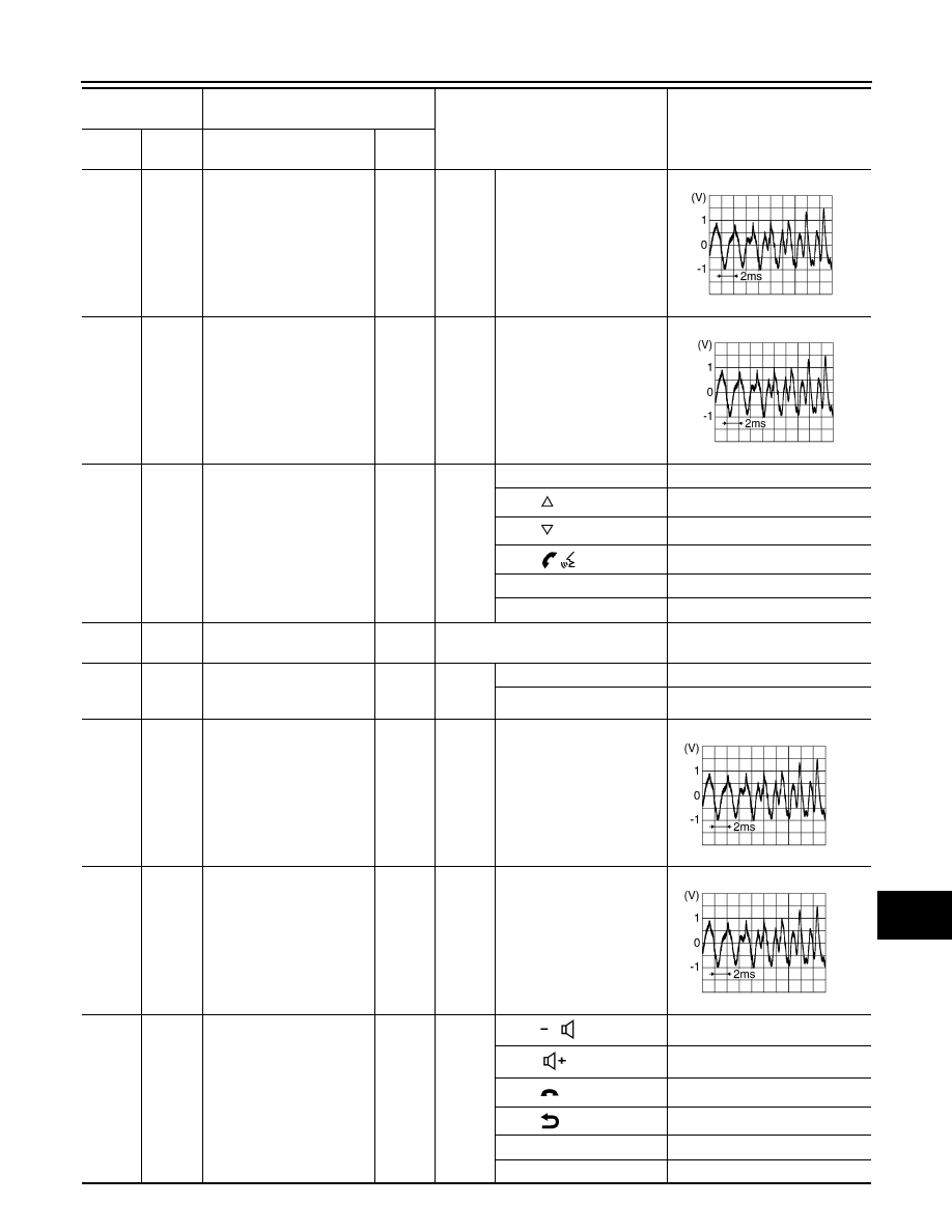
(V)
Sound signal front door
speaker and instrument
panel tweeter LH
Output
Ignition
switch
ON
Audio output
36
(BR)
37
(Y)
Sound signal rear door
speaker LH
Output
Ignition
switch
ON
Audio output
38
(G)
47
(B)
Steering switch signal A
Input
Ignition
switch
ON
Press SOURCE switch
0V
Press
switch
1.0V
Press
switch
2.0V
Press
switch
3.0V
Press ENTER switch
4.0V
Except above
5.0V
39
(P)
Ground
ACC power supply
Input
Ignition switch ACC
Battery voltage
41
(R)
Ground
Illumination signal
Input
Ignition
switch
OFF
Lighting switch OFF
0 V
Lighting switch ON
Battery voltage
43
(BR)
44
(Y)
Sound signal front door
speaker and instrument
panel tweeter RH
Output
Ignition
switch
ON
Audio output
45
(L)
46
(SB)
Sound signal rear door
speaker RH
Output
Ignition
switch
ON
Audio output
48
(W)
47
(B)
Steering switch signal B
Input
Ignition
switch
ON
Press
switch
0V
Press
switch
1.0V
Press
switch
2.0V
Press
switch
3.0V
Press DISP switch
4.0V
Except above
5.0V
Terminal No.
(Wire color)
Description
Condition
Value
(Approx.)
+
–
Signal name
Input/
Output
SKIB3609E
SKIB3609E
SKIB3609E
SKIB3609E