Nissan Teana J32. Manual - part 491
EM-88
< DISASSEMBLY AND ASSEMBLY >
CAMSHAFT
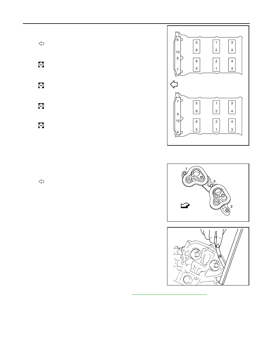
5.
Tighten camshaft bracket bolts in the following steps, in numeri-
cal order as shown in the figure.
a.
Tighten No. 7 to 10 in order as shown.
b.
Tighten No. 1 to 6 in order as shown.
c.
Tighten No. 1 to 10 in numerical order as shown.
d.
Tighten No. 1 to 10 in numerical order as shown.
CAUTION:
After tightening mounting bolts of camshaft brackets (No.
1), be sure to wipe off excessive liquid gasket from the
parts list below.
• Mating surface of rocker cover
• Mating surface of rear timing chain case
6.
Tighten camshaft sensor bracket bolts in numerical order as
shown in the figure.
NOTE:
The order of tightening bolts in the same for bank 1 and bank 2.
7.
Measure difference in levels between front end faces of cam-
shaft bracket (No. 1) and cylinder head.
• Measure two positions (both intake and exhaust side) for a
single bank.
• If the measured value is out of the standard, reinstall camshaft
bracket (No. 1).
8.
Inspect and adjust the valve clearance. Refer to
EM-17, "Inspection and Adjustment"
.
9.
Install in the reverse order of removal after this step.
Inspection
INFOID:0000000003802285
INSPECTION AFTER REMOVAL
Camshaft Runout
1.
Put V-block on precise flat table, and support No. 2 and 4 journals of camshaft.
: Engine front
: 1.96 N·m (0.20 kg-m, 1 ft-lb)
: 1.96 N·m (0.20 kg-m, 1 ft-lb)
: 5.88 N·m (0.60 kg-m, 4 ft-lb)
: 10.4 N·m (1.1 kg-m, 8 ft-lb)
: Engine front
JPBIA0257ZZ
JPBIA1960ZZ
Standard
:
−
0.14 to 0.14 mm (
−
0.0055 to 0.0055 in)
EMQ0044D