содержание .. 728 729 730 731 ..
Nissan Murano Z51. Manual - part 730
PARKING LAMP CIRCUIT
EXL-231
< DTC/CIRCUIT DIAGNOSIS >
[HALOGEN TYPE]
C
D
E
F
G
H
I
J
K
M
A
B
EXL
N
O
P
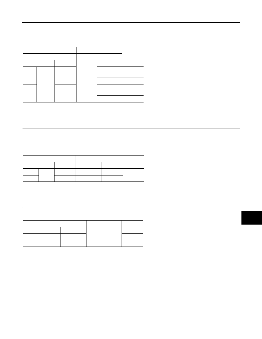
4.
With operating the test items, check the voltage between the IPDM E/R harness connector and the
ground.
Is the measurement value normal?
YES
>> GO TO 5.
NO
>> Replace IPDM E/R.
5.
CHECK PARKING LAMP OPEN CIRCUIT
1.
Turn the ignition switch OFF.
2.
Disconnect IPDM E/R connector.
3.
Check continuity between the IPDM E/R harness connector and the front combination lamp harness con-
nector.
Does continuity exist?
YES
>> GO TO 6.
NO
>> Repair the harnesses or connectors.
6.
CHECK PARKING LAMP GROUND OPEN CIRCUIT
Check continuity between the front combination lamp harness connector and the ground.
Does continuity exist?
YES
>> Replace the front combination lamp.
NO
>> Repair the harnesses or connectors.
Terminals
Test item
Voltage
(Approx.)
(+)
(
−
)
IPDM E/R
Ground
EXTERNAL
LAMPS
Connector
Terminal
RH
E346
91
TAIL
Battery
voltage
Off
0 V
LH
92
TAIL
Battery
voltage
Off
0 V
IPDM E/R
Front combination lamp
Continuity
Connector
Terminal
Connector
Terminal
RH
E346
91
E319
1
Existed
LH
92
E318
1
Front combination lamp
Ground
Continuity
Connector
Terminal
RH
E319
2
Existed
LH
E318
2