содержание .. 651 652 653 654 ..
Nissan Murano Z51. Manual - part 653
EM-84
< UNIT REMOVAL AND INSTALLATION >
ENGINE ASSEMBLY
8.
Remove strut assembly and steering knuckle fixing nuts and bolts. Refer to
9.
Remove front wheel sensor (RH and LH) for ABS from steering knuckle. Refer to
10. Remove front brake caliper assembly with piping connected, and temporarily secure it to aside for vehicle
side. Refer to
BR-36, "BRAKE CALIPER ASSEMBLY : Exploded View"
.
11. Disconnect power steering piping at a point between vehicle and engine. Refer to
.
• Install plug to avoid leakage of power steering fluid.
12. Remove rear plate cover from oil pan (upper). Then remove bolts fixing drive plate to torque converter.
TM-173, "Removal and Installation"
.
13. Remove transaxle joint bolts which pierce at oil pan (upper) lower rear side. Refer to
.
14. Remove crankshaft position sensor (POS). Refer to
CAUTION:
• Handle carefully to avoid dropping and shocks.
• Never disassemble.
• Never allow metal powder to adhere to magnetic part at sensor tip.
• Never place sensors in a location where they are exposed to magnetism.
Removal
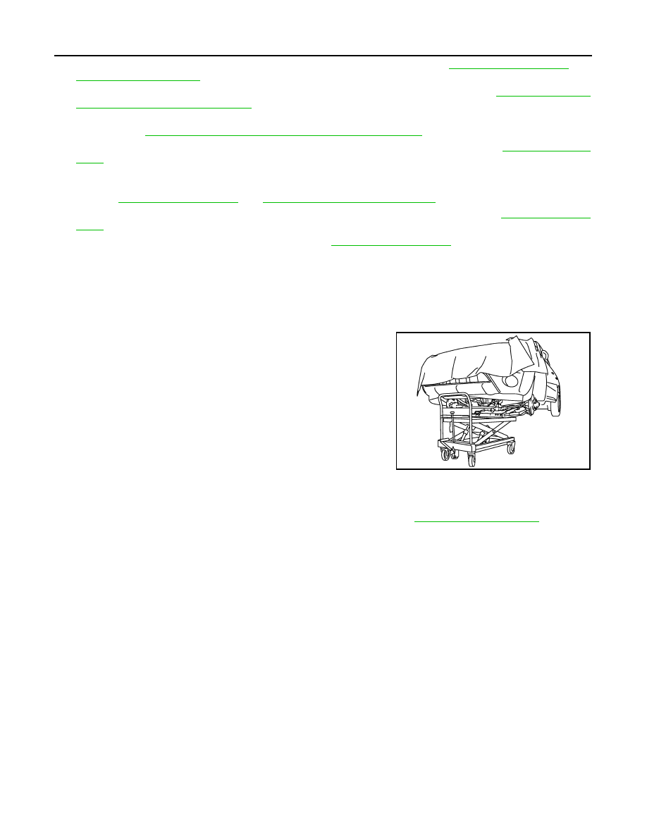
1.
Use a manual lift table caddy (commercial service tool) or equiv-
alently rigid tool such as a transmission jack. Securely support
bottom of front suspension member.
CAUTION:
Put a piece of wood or something similar as the supporting
surface, secure a completely stable condition.
2.
Remove engine mounting insulator (RH) and engine mounting bracket (RH).
3.
Remove mounting bolt between transverse link and front suspension member with power tool.
4.
Remove front suspension member mounting nuts and bolts. Refer to
.
5.
Carefully lower jack, or raise lift to remove the engine, the transaxle and transfer assembly and front sus-
pension member. When performing work, observe the following caution:
CAUTION:
• Confirm there is no interference with the vehicle.
• Check all connection points have been disconnected.
• Keep in mind the center of vehicle gravity changes. If necessary, use jack(s) to support the vehi-
cle at rear jacking point(s) to prevent it from falling it off the lift.
Separation
PBIC1190E