Nissan Murano Z51. Manual - part 346


  Главная      Nissan     Nissan Murano Z51 (2010 year) - Service Manual


поиск по сайту            


содержание   ..  344  345  346  347   ..


Nissan Murano Z51. Manual - part 346


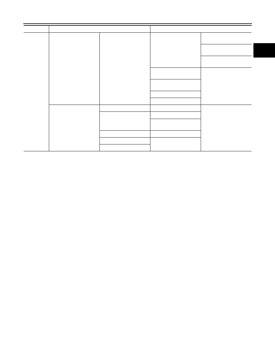
OVERHEATING CAUSE ANALYSIS

CO-5

< SYMPTOM DIAGNOSIS >

C

D

E

F

G

H

I

J

K

L

M

A

CO

N

P

O

Except cool-
ing system 
parts mal-
function

Overload on engine

Abusive driving

High engine rpm under no 
load

Driving in low gear for ex-
tended time

Driving at extremely high 
speed

Powertrain system malfunc-
tion

Installed improper size 
wheels and tires

Dragging brakes

Improper ignition timing

Blocked or restricted air 
flow

Blocked bumper

Blocked radiator grille

Installed car brassiere

Mud contamination or paper 
clogging

Blocked radiator

Blocked condenser

Blocked air flow

Installed large fog lamp

Symptom

Check items

CO-6

< PRECAUTION >

PRECAUTIONS

PRECAUTION

PRECAUTIONS

FOR USA AND CANADA

FOR USA AND CANADA : Precaution for Supplemental Restraint System (SRS) "AIR 
BAG" and "SEAT BELT PRE-TENSIONER"

INFOID:0000000005681920

The Supplemental Restraint System such as “AIR BAG” and “SEAT BELT PRE-TENSIONER”, used along
with a front seat belt, helps to reduce the risk or severity of injury to the driver and front passenger for certain
types of collision. This system includes seat belt switch inputs and dual stage front air bag modules. The SRS
system uses the seat belt switches to determine the front air bag deployment, and may only deploy one front
air bag, depending on the severity of a collision and whether the front occupants are belted or unbelted.
Information necessary to service the system safely is included in the “SRS AIR BAG” and “SEAT BELT” of this
Service Manual.

WARNING:

• To avoid rendering the SRS inoperative, which could increase the risk of personal injury or death in

the event of a collision which would result in air bag inflation, all maintenance must be performed by
an authorized NISSAN/INFINITI dealer.

• Improper maintenance, including incorrect removal and installation of the SRS, can lead to personal

injury caused by unintentional activation of the system. For removal of Spiral Cable and Air Bag
Module, see the “SRS AIR BAG”.

• Do not use electrical test equipment on any circuit related to the SRS unless instructed to in this

Service Manual. SRS wiring harnesses can be identified by yellow and/or orange harnesses or har-
ness connectors.

PRECAUTIONS WHEN USING POWER TOOLS (AIR OR ELECTRIC) AND HAMMERS

WARNING:

• When working near the Air Bag Diagnosis Sensor Unit or other Air Bag System sensors with the

ignition ON or engine running, DO NOT use air or electric power tools or strike near the sensor(s)
with a hammer. Heavy vibration could activate the sensor(s) and deploy the air bag(s), possibly
causing serious injury.

• When using air or electric power tools or hammers, always switch the ignition OFF, disconnect the

battery, and wait at least 3 minutes before performing any service.

FOR USA AND CANADA : Liquid Gasket

INFOID:0000000005518087

REMOVAL OF LIQUID GASKET SEALING

• After removing mounting nuts and bolts, separate the mating sur-

face using the seal cutter [SST: KV10111100 (J-37228)] (A) and
remove old liquid gasket sealing.     

CAUTION:

Be careful not to damage the mating surfaces.

• Tap (B) the seal cutter [SST: KV10111100 (J-37228)] to insert it,

and then slide (C) it by tapping on the side as shown in the figure.

• In areas where seal cutter [SST: KV10111100 (J-37228)] is difficult

to use, use a plastic hammer to lightly tap the parts, to remove it.

CAUTION:

If for some unavoidable reason tool such as a screwdriver is
used, be careful not to damage the mating surfaces.

LIQUID GASKET APPLICATION PROCEDURE

JPBIA0052ZZ

PRECAUTIONS

CO-7

< PRECAUTION >

C

D

E

F

G

H

I

J

K

L

M

A

CO

N

P

O

1.

Using a scraper (A), remove old liquid gasket adhering to the liq-
uid gasket application surface and the mating surface.
• Remove liquid gasket completely from the groove of the liquid

gasket application surface, mounting bolts, and bolt holes.

2.

Wipe the liquid gasket application surface and the mating sur-
face with white gasoline (lighting and heating use) to remove
adhering moisture, grease and foreign materials.

3.

Attach liquid gasket tube to the tube presser (commercial ser-
vice tool).
Use Genuine RTV Silicone Sealant or equivalent. Refer to

GI-18, "Recommended Chemical Products and Sealants"

.

4.

Apply liquid gasket without breaks to the specified location with
the specified dimensions.
• If there is a groove for the liquid gasket application, apply liq-

uid gasket to the groove.

• As for the bolt holes (B), normally apply liquid gasket inside

the holes. Occasionally, it should be applied outside the holes.
Check to read the text of service manual.

• Within five minutes of liquid gasket application, install the mat-

ing component.

• If liquid gasket protrudes, wipe it off immediately.
• Never retighten after mounting bolts and nuts the installation.
• After 30 minutes or more have passed from the installation, fill

engine oil and engine coolant.

CAUTION:

If there are specific instructions in this manual, observe them.

FOR MEXICO

FOR MEXICO : Precaution for Supplemental Restraint System (SRS) "AIR BAG" and 
"SEAT BELT PRE-TENSIONER"

INFOID:0000000005681924

The Supplemental Restraint System such as “AIR BAG” and “SEAT BELT PRE-TENSIONER”, used along
with a front seat belt, helps to reduce the risk or severity of injury to the driver and front passenger for certain
types of collision. Information necessary to service the system safely is included in the “SRS AIR BAG” and
“SEAT BELT” of this Service Manual.

WARNING:

• To avoid rendering the SRS inoperative, which could increase the risk of personal injury or death in

the event of a collision which would result in air bag inflation, all maintenance must be performed by
an authorized NISSAN/INFINITI dealer.

• Improper maintenance, including incorrect removal and installation of the SRS, can lead to personal

injury caused by unintentional activation of the system. For removal of Spiral Cable and Air Bag
Module, see the “SRS AIR BAG”.

• Do not use electrical test equipment on any circuit related to the SRS unless instructed to in this

Service Manual. SRS wiring harnesses can be identified by yellow and/or orange harnesses or har-
ness connectors.

JPBIA0053ZZ

EMA0622D

A

:  Groove

: Inside

JPBIA0010ZZ

CO-8

< PRECAUTION >

PRECAUTIONS

PRECAUTIONS WHEN USING POWER TOOLS (AIR OR ELECTRIC) AND HAMMERS

WARNING:

• When working near the Air Bag Diagnosis Sensor Unit or other Air Bag System sensors with the

ignition ON or engine running, DO NOT use air or electric power tools or strike near the sensor(s)
with a hammer. Heavy vibration could activate the sensor(s) and deploy the air bag(s), possibly
causing serious injury.

• When using air or electric power tools or hammers, always switch the ignition OFF, disconnect the

battery, and wait at least 3 minutes before performing any service.

FOR MEXICO : Liquid Gasket

INFOID:0000000005681910

REMOVAL OF LIQUID GASKET SEALING

• After removing mounting nuts and bolts, separate the mating sur-

face using the seal cutter [SST: KV10111100 (J-37228)] (A) and
remove old liquid gasket sealing.     

CAUTION:

Be careful not to damage the mating surfaces.

• Tap (B) the seal cutter [SST: KV10111100 (J-37228)] to insert it,

and then slide (C) it by tapping on the side as shown in the figure.

• In areas where seal cutter [SST: KV10111100 (J-37228)] is difficult

to use, use a plastic hammer to lightly tap the parts, to remove it.

CAUTION:

If for some unavoidable reason tool such as a screwdriver is
used, be careful not to damage the mating surfaces.

LIQUID GASKET APPLICATION PROCEDURE

1.

Using a scraper (A), remove old liquid gasket adhering to the liq-
uid gasket application surface and the mating surface.
• Remove liquid gasket completely from the groove of the liquid

gasket application surface, mounting bolts, and bolt holes.

2.

Wipe the liquid gasket application surface and the mating sur-
face with white gasoline (lighting and heating use) to remove
adhering moisture, grease and foreign materials.

3.

Attach liquid gasket tube to the tube presser (commercial ser-
vice tool).
Use Genuine RTV Silicone Sealant or equivalent. Refer to

GI-18, "Recommended Chemical Products and Sealants"

.

4.

Apply liquid gasket without breaks to the specified location with
the specified dimensions.
• If there is a groove for the liquid gasket application, apply liq-

uid gasket to the groove.

JPBIA0052ZZ

JPBIA0053ZZ

EMA0622D


содержание   ..  344  345  346  347   ..