содержание .. 214 215 216 217 ..
Nissan Murano Z51. Manual - part 216
AV
AUX IMAGE SIGNAL CIRCUIT
AV-643
< DTC/CIRCUIT DIAGNOSIS >
[BOSE AUDIO WITH NAVIGATION]
C
D
E
F
G
H
I
J
K
L
M
B
A
O
P
AUX IMAGE SIGNAL CIRCUIT
Description
INFOID:0000000005528778
Transmits the image signal of external device from auxiliary input jacks to front display unit.
Diagnosis Procedure
INFOID:0000000005528779
1.
CHECK CONTINUITY AUX IMAGE SIGNAL CIRCUIT
1.
Turn ignition switch OFF.
2.
Disconnect auxiliary input jacks connector and front display unit connector.
3.
Check continuity between auxiliary input jacks harness connector and front display unit harness connec-
tor.
4.
Check continuity between front display unit harness connector and ground.
Is the inspection result normal?
YES
>> GO TO 2.
NO
>> Repair harness or connector.
2.
CHECK AUX IMAGE SIGNAL
1.
Connect auxiliary input jacks connector and front display unit connector.
2.
Turn ignition switch ON.
3.
Check signal between AV control unit harness connector using an oscilloscope.
Is the inspection result normal?
YES
>> Replace front display unit.
NO
>> Check that there is no malfunction in the external device.
Auxiliary input jacks
Front display unit
Continuity
Connector
Terminals
Connector
Terminals
M253
7
M49
15
Existed
8
5
Front display unit
Ground
Continuity
Connector
Terminal
M49
15
Not existed
(+)
(
−
)
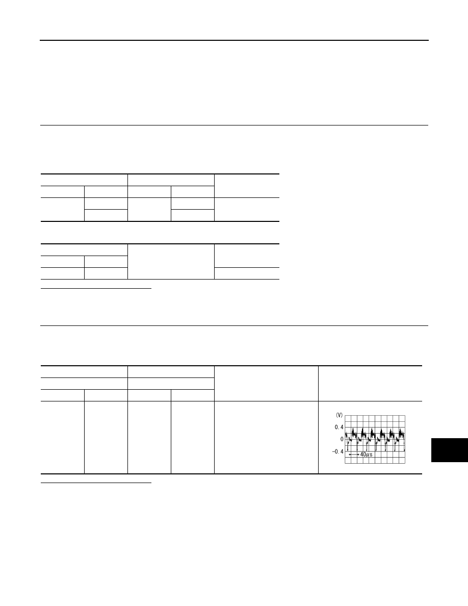
Condition
Signal
Front display unit
Front display unit
Connector
Terminal
Connector
Terminal
M49
15
M49
5
When AUX image is displayed.
SKIB2251J